Environmental equipment, instruments and meters, robots, ...

Overview
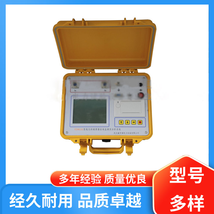
The Insulation Resistance Tester is suitable for products such as motors, transformers, and electrical coils, which are wound with enameled wire.
Due to the inherent quality issues with the insulation coating of the wire enameling, as well as accidental damage to the insulation layer during processes such as winding, inserting, scraping, terminal shaping, insulation dipping, and assembly, the insulation strength between coil layers or between turns can decrease. This consequently affects the quality and reliability of electrical equipment.
To enhance product quality and lifespan, ensuring that the insulation between the winding layers or turns of the component's enameled wire is excellent is essential. Therefore, conducting this test on the product is imperative.
According to our nationGB14711-93Standard for General Safety Requirements of Small and Medium-sized Rotating Electric MachinesGB755-87Basic Technical Requirements for Rotating Electric Machines standard and national standardGBT22714-2008_"Standards such as 'Specification for Interleaving Insulation Test of Low-Voltage Motor Winding Coils' require that both finished and semi-finished motor products undergo withstand voltage insulation tests between turns before and after varnishing.
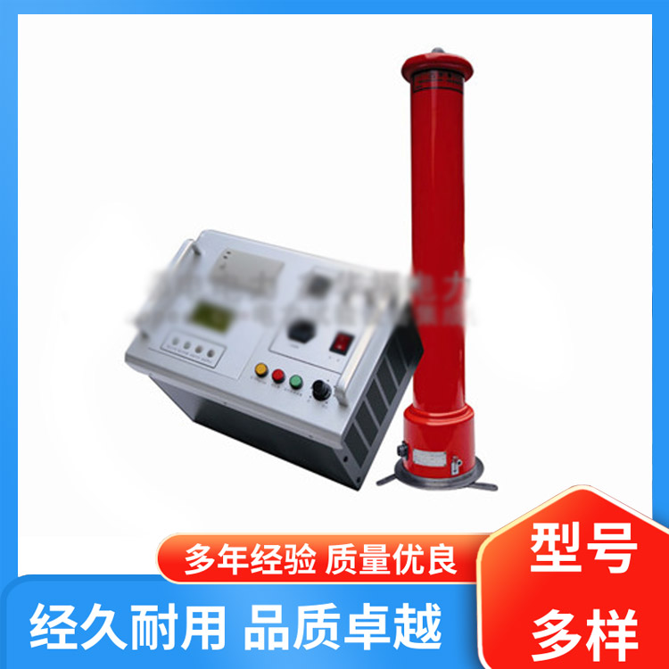
The Insulation Resistance Tester utilizes the pulse waveform comparison method to simulate equivalent overvoltage tests on the coil windings of motors and electrical equipment using high-voltage pulses. By observing, comparing, and analyzing the waveform displayed by the instrument, it can quickly and accurately determine the quality of the insulation between the windings. It has excellent distinguishing capabilities for various insulation faults such as inter-turn short circuits, coil corona discharge, local short circuits, wiring errors, and coil unbalance.
The entire unit of the insulation resistance tester has a high degree of electronic integration. The test waveform can be observed on the oscilloscope built into the tester, and the peak voltage can be directly read on the digital meter.YAxial AmplitudeXAxial scanning speed is continuously adjustable, with the entire machine featuring high precision and low failure rate.,All performance and technical indicators have reached the advanced level domestically.
This instrument is in line withGB755-87、GB14711-93A new type of standard instrument is an indispensable means to enhance the testing level and reliability of motor insulation in our country.

The Insulation Resistance Tester can check for the following faults:
Insulation Breakdown in Transformers
Corona Discharge
Wiring mistake, incorrect wire embedding
Winding Breakage
Odometer Discrepancy
Alternating between earth and winding, or localized short circuits between windings and the core.
Interleaving and layer insulation strength tests for single-phase, three-phase small and medium-sized motors, micro motors, special motors, electric tool motors, transformers (including switch-mode power supply transformers), relays, and electrical appliances with electromagnetic wire windings.
Testing Basic Principles
It is well-known that when a coil experiences a direct solid short-circuit fault, it forms short-circuit turns, which significantly alter the coil's inductance, capacitance, and resistance. For the inter-turn insulation, which still has a certain degree of insulation, there is no noticeable change in the winding inductance, resistance, and capacitance before it reaches the point of puncturing and exposing the weak spot. Therefore, the fault cannot be observed. Only when the test voltage exceeds the insulation weak spot's withstand voltage, will inter-turn insulation puncture occur, resulting in spark discharge, accompanied by a discharge sound and ozone, while also significantly altering the inductance...LCapacitorCNo Chinese content provided.RTherefore, it will alter the decay oscillation frequency and rate of the impulse test voltage wave in the winding.
The Insulation Resistance Test Instrument is based on the aforementioned principle and employs...The "Pulse Waveform Comparison Method" is used to test impedance symmetry and balance conditions. This involves alternatingly applying pulses of voltage with specific rise times and peak values to the sample and reference items. The difference in the decaying waveforms caused by the pulse voltage in both is used to differentiate between motor winding insulation faults. The degree of difference reflects the severity of the winding fault, and due to the short pulse wavefront time and low energy of the applied high-voltage pulses, it is considered a non-destructive test.


www.114global.com © Zhongshang 114 Hebei Network Technology Co., Ltd.Address: Room 6009, Oriental New World Center, No.118 East Zhongshan Road, Qiaoxi District, Shijiazhuang City, Hebei ProvincePlatform Service Hotline: 4006299930