Environmental equipment, instruments and meters, robots, ...

Summary
Isolation switches are high-voltage switchgear with extensive usage and a wide range of applications in the power system. Due to outdoor isolation switches beingPlease provide the Chinese content you would like translated into American English..Electrical equipment that is fully exposed to the atmospheric environment and directly affected by environmental and climatic conditions operates under harsh conditions, making it prone to mechanical or electrical failures. Particularly, the contact parts are susceptible to damage from rain, dust, and harmful gases, leading to poor contact and subsequent overheating. The springs providing contact pressure may lose their tension due to overheating, further exacerbating the issue. This creates a vicious cycle where overheating causes the contact tips to burn out, leading to accidents. During maintenance, there is often a focus on replacing visibly failed or broken springs, but those with reduced tension are often overlooked. As a result, during subsequent operation, the distribution of current among the contact tips varies due to differing pressures, with greater discrepancies leading to uneven current distribution. Over time, this can result in poor contact and overheating. The overheating can spread from one contact tip to the entire contact point, leading to poor contact. Additionally, many isolation switches have adjustable contact tip pressure. If the pressure is not adjusted adequately during maintenance or if there are differences in the adjustment pressure for each contact tip, the aforementioned issues can also arise.
Currently, the vast majority of maintenance personnel judge the contact quality of conductive parts by measuring their circuit resistance, believing that if the circuit resistance is within the acceptable range, the maintenance of the conductive parts can be completed successfully. However, this is not the case. The circuit resistance values provided in the product manual are for the entire conductive loop, including the bulk resistance and contact resistance of components such as terminal blocks, conductive tubes, and contact tips, which have a wide range and ample margin. They cannot directly reflect the changes in contact resistance but can only indicate that the conductive loop is open. Tests have shown that the circuit resistance values for both two-pair and four-pair contact tips are within the acceptable range. Similarly, the pressure of the contact tips does not significantly affect the circuit resistance values.
Regulations for measuring contact pressure of measuring fingers are present in various maintenance procedures and standards, with a recommended tool being a spring scale. In practical operations, measuring the contact pressure of measuring fingers at high altitudes is not only inconvenient and inaccurate but also unsafe. For some structures, such as scissor-type disconnect switches, the contact pressure of the measuring fingers cannot be measured with a spring scale at all. Therefore, the requirement for measuring the contact pressure of measuring fingers is merely a piece of paper with no practical application.
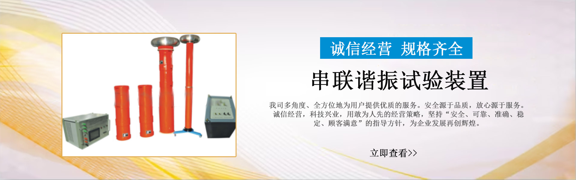
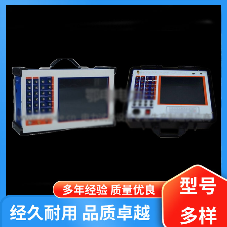
In response to the current maintenance status of the power supply system, our company has independently developed an intelligent testing device for measuring the contact pressure of high-voltage disconnecting switch fingers. By simply opening the sensor of the testing clamp to simulate the contactor at each contact position of the fingers, it can display the contact pressure at that moment and remember it. This effectively resolves a major challenge in measuring finger pressure.
This instrument can also be used by switchgear manufacturers for testing the contact finger pressure; altering the shape of the pressure sensor can also measure the contact finger pressure of circuit breakers.

Key Technical Parameters
Work Environment:-20~40℃,≤80%RH Atmospheric Pressure86~106kpa
Power Voltage:AC220V±10% 50Hz±10% Or, battery power inside the device: ≤20 W
Measurement Range:≤1000 N Error: ≤1%
Measure Diameter (Finger Spacing):5.5mm~90mm Greater90mmCustomizable
Built-in lithium battery, power working time:≥6Hourly ( customizable ). Charging method:a)Charge the battery via the dedicated charger and interface panel.b)PanelAC220VPlug Charging
Sensor Signal Wire Length:10m
Insulation Resistance >2MΩ
Dielectric Strength Power supply to the case with industrial frequency1.5KVN/A1Minutes, no flashovers or arcovers.


www.114global.com © Zhongshang 114 Hebei Network Technology Co., Ltd.Address: Room 6009, Oriental New World Center, No.118 East Zhongshan Road, Qiaoxi District, Shijiazhuang City, Hebei ProvincePlatform Service Hotline: 4006299930