Environmental equipment, instruments and meters, robots, ...

1Summary
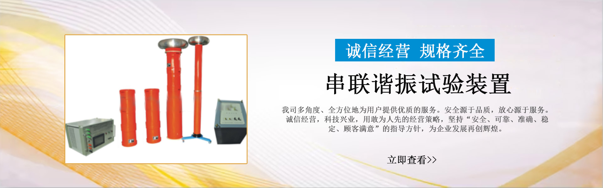
The integrated partial discharge location system is primarily used for partial discharge diagnosis of medium-voltage cables. The system's test frequency is20HzTo several hundred hertz of damped AC voltageDAC)。
The integrated partial discharge location system is primarily used for partial discharge diagnosis of medium-voltage cables. The system's test frequency is20HzAC voltage damping up to several hundred hertzDACThe damping AC voltage during the system's testing phase can reach up to...30kVIntegrating advanced system hardware and software for diagnostics, the software system encompassesVLFPlease provide the Chinese content to be translated.DACOur on-site voltage testing combines non-destructive partial discharge testing with dielectric loss measurement, serving as a fundamental and effective testing method for the operation, maintenance, and repair of cables. It encompasses nearly all medium-voltage cable types, such as...XPLEAnd the necessary test voltages for paper-insulated cables and diagnostic tools.
Damping AC voltage as high as can be achieved during the system's testing process30kV, and utilizes advanced system hardware and software for diagnostics, including:
-New transistor technology and laser control techniques, such as high-voltage transistor switches.
-Electronic components, digital signal processing, such as high-voltage transistor switches, high-voltage sources.
-Digital Signal Processors and Filters
-Wireless connections and built-in computer systems, including partial discharge detectors, control units, and partial discharge analyzers.

1Hardware
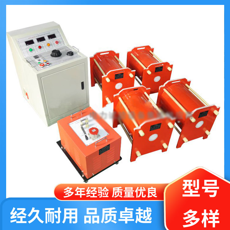
High-voltage Units: High-voltage coils, high-voltage voltage dividers, high-voltage switches, partial discharge couplers, coupling units, and partial discharge detectors.
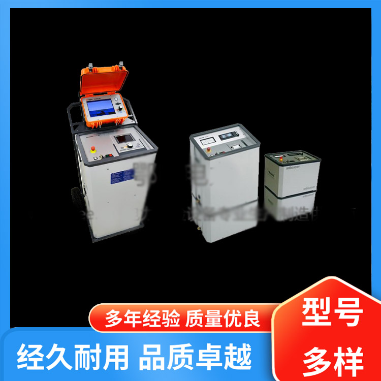
Control Unit: The notebook unit is primarily used for controlling test programs, analyzing test data, and storing test data. External connections are high voltage, with control switches for regulating high voltage pressure. After grounding the system and making internal connections, it is then connected to the cable being tested.
2Software
The main components of the software are as follows:
Test analysis software serves as the main interface for user operations; the software is controlled by a laptop. The software is capable of performing the following functions:
-Define Test Objects
-Calibrate test circuit
-Pressure Test
-Test and save test data.
The browsing software is integrated into the system but can also be installed independently as per customer requirements. The primary uses of the software are as follows:
-Display and manage test data, generate test reports.
-Utilize a pulse reflectometer to analyze test data.
-Generate database features.
The user interface is controlled by the mouse and keyboard. Each key on the screen is labeled with its corresponding function. Every active function key is capable of performing the respective function or directly accessing the next operation interface. Click“EscPress the key to return to the system's starting interface.
The interface display and functionalities of the software can be summarized as follows:
Tested Cable: Define the parameters of the tested cable system.
Test Calibration: Initiate and execute calibration of the test circuit.
Field Diagnostics: Conducting tests and saving data to diagnose power cables on-site.
Review Report: Analyze data and generate test reports.


www.114global.com © Zhongshang 114 Hebei Network Technology Co., Ltd.Address: Room 6009, Oriental New World Center, No.118 East Zhongshan Road, Qiaoxi District, Shijiazhuang City, Hebei ProvincePlatform Service Hotline: 4006299930