зҺҜдҝқи®ҫеӨҮгҖҒд»ӘеҷЁд»ӘиЎЁгҖҒжңәеҷЁдәәгҖҒе…»иҖҒи®ҫеӨҮгҖҒе...

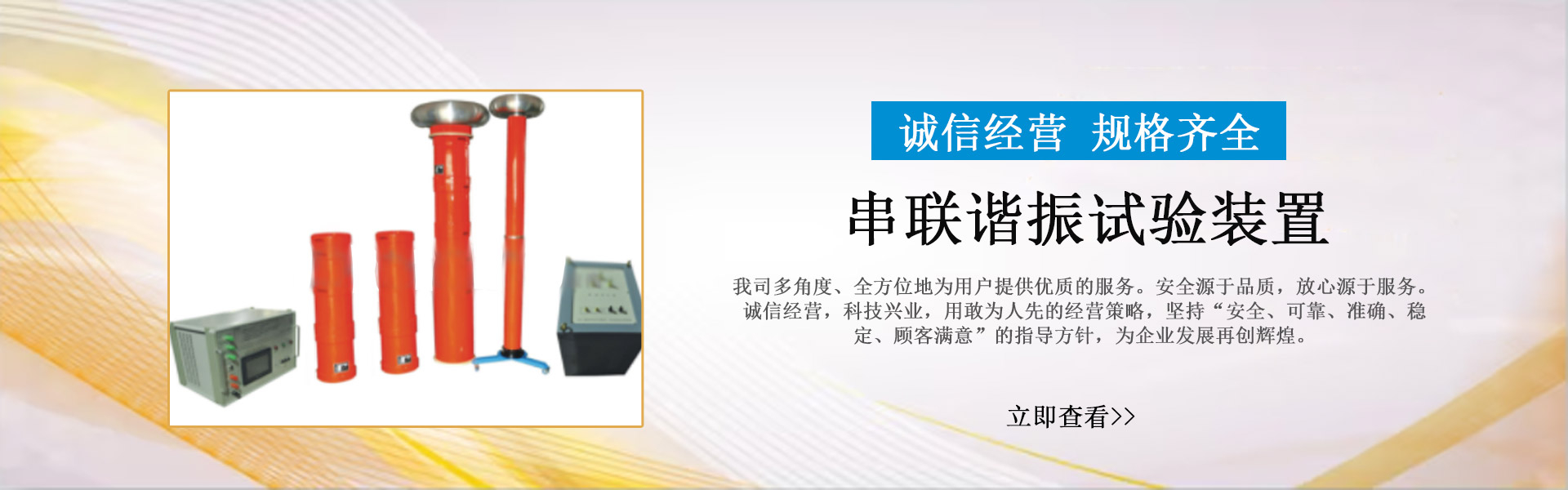
дёҖ.жҰӮиҝ°
йҡ”зҰ»ејҖе…іжҳҜз”өеҠӣзі»з»ҹдёӯдҪҝз”ЁйҮҸеӨ§еә”з”ЁиҢғеӣҙе№ҝжіӣзҡ„й«ҳеҺӢејҖе…іи®ҫеӨҮгҖӮз”ұдәҺжҲ·еӨ–йҡ”зҰ»ејҖе…іжҳҜе”Ҝ.дёҖе®Ңе…ЁжҡҙйңІеңЁеӨ§ж°”зҺҜеўғдёӯе·ҘдҪңгҖҒеҸ—зҺҜеўғж°”еҖҷжқЎд»¶еҪұе“ҚзӣҙжҺҘе’ҢдёҘйҮҚзҡ„з”өж°”и®ҫеӨҮпјҢе®ғзҡ„иҝҗиЎҢжқЎд»¶жҜ”иҫғжҒ¶еҠЈпјҢе®№жҳ“дә§з”ҹжңәжў°жҲ–з”өж°”ж–№йқўзҡ„ж•…йҡңгҖӮе°Өе…¶жҳҜи§ҰжҢҮжҺҘи§ҰйғЁеҲҶе®№жҳ“еҸ—йӣЁж°ҙгҖҒзҒ°е°ҳеҸҠжңүе®іж°”дҪ“зҡ„дҫөиўӯдә§з”ҹжҺҘи§ҰдёҚиүҜиҖҢеҜјиҮҙеҸ‘зғӯпјҢжҸҗдҫӣи§ҰжҢҮеҺӢеҠӣзҡ„еј№з°§дјҡеӣ еҸ‘зғӯиҖҢйҖҖзҒ«дҪҝеҺӢеҠӣйҷҚдҪҺпјҢиҝҷж ·жӣҙеҜјиҮҙи§ҰжҢҮеҸ‘зғӯеҪўжҲҗжҒ¶жҖ§еҫӘзҺҜз»Ҳзғ§еқҸи§ҰжҢҮй…ҝжҲҗдәӢж•…гҖӮеңЁжЈҖдҝ®ж—¶еҫҖеҫҖеҸӘжіЁж„ҸжӣҙжҚўжҳҺжҳҫеӨұж•Ҳе’Ңж–ӯиЈӮзҡ„еј№з°§пјҢиҖҢеҜ№йӮЈдәӣеҺӢеҠӣйҷҚдҪҺзҡ„еј№з°§ж— жі•еҲӨж–ӯдёҺжӣҙжҚўпјҢиҝҷж ·еңЁеҶҚж¬ЎиҝҗиЎҢдёӯпјҢжҜҸдёӘи§ҰжҢҮз”өжөҒзҡ„еҲҶеёғдјҡеӣ еҺӢеҠӣдёҚеҗҢиҖҢдёҚеҗҢпјҢе·®еҲ«и¶ҠеӨ§з”өжөҒеҲҶеёғи¶ҠдёҚеқҮеҢҖпјҢй•ҝжңҹиҝҗиЎҢеҗҺе°ұдјҡеҸ‘з”ҹжҺҘи§ҰдёҚиүҜиҖҢиҝҮзғӯгҖӮи§ҰжҢҮзҡ„еҸ‘зғӯдјҡжҒ¶жҖ§еҫӘзҺҜпјҢдёҖдёӘи§ҰжҢҮжҺҘи§ҰдёҚеҘҪе°ұдјҡ漫延ж•ҙдёӘи§ҰеӨҙжҺҘи§ҰдёҚиүҜгҖӮеҗҢж—¶жңүдёҚе°‘йҡ”зҰ»ејҖе…ізҡ„и§ҰжҢҮеҺӢеҠӣеҸҜи°ғпјҢеҰӮжһңеңЁжЈҖдҝ®ж—¶и°ғж•ҙеҺӢеҠӣдёҚеӨҹжҲ–жҜҸдёӘи§ҰжҢҮзҡ„и°ғж•ҙеҺӢеҠӣжңүе·®еҲ«еҗҢж ·дјҡеҮәзҺ°дёҠиҝ°зҺ°иұЎгҖӮ
зӣ®еүҚз»қеӨ§йғЁеҲҶжЈҖдҝ®дәәе‘ҳеҲӨж–ӯеҜјз”өйғЁеҲҶжҺҘи§ҰеҘҪеқҸзҡ„еҲӨжҚ®е°ұжҳҜжөӢйҮҸе…¶еӣһи·Ҝз”өйҳ»пјҢи®Өдёәеӣһи·Ҝз”өйҳ»еңЁеҗҲж јиҢғеӣҙеҶ…пјҢеҜјз”өйғЁеҲҶзҡ„жЈҖдҝ®е·ҘдҪңе°ұеҸҜеңҶж»Ўз»“жқҹгҖӮе…¶е®һдёҚ然пјҢеңЁдә§е“ҒиҜҙжҳҺд№Ұдёӯз»ҷеҮәзҡ„еӣһи·Ҝз”өйҳ»еҖјжҳҜж•ҙдёӘеҜјз”өеӣһи·Ҝзҡ„еҖјпјҢе®ғеҢ…жӢ¬жҺҘзәҝз«ҜеӯҗгҖҒеҜјз”өз®ЎгҖҒи§ҰжҢҮи§ҰеӨҙзӯүйғЁеҲҶзҡ„дҪ“з”өйҳ»еҸҠжҺҘи§Ұз”өйҳ»пјҢиҢғеӣҙиҫғеӨ§гҖҒиЈ•еәҰиҫғеӨ§пјҢдёҚиғҪзӣҙжҺҘеҸҚжҳ жҺҘи§Ұз”өйҳ»зҡ„еҸҳеҢ–пјҢеҸӘиғҪиҜҙжҳҺеҜјз”өеӣһи·ҜйҖҡи·ҜгҖӮиҜ•йӘҢиЎЁжҳҺпјҡдёӨеҜ№еҜ№и§ҰжҢҮжҺҘи§ҰдёҺеӣӣеҜ№и§ҰжҢҮжҺҘи§Ұе…¶еӣһи·Ҝз”өйҳ»еҖјеқҮеңЁеҗҲж јиҢғеӣҙеҶ…гҖӮеҗҢж ·и§ҰжҢҮеҺӢеҠӣеӨ§дёҺе°Ҹеӣһи·Ҝз”өйҳ»еҖјд№ҹеҹәжң¬жІЎжңүеҸҳеҢ–гҖӮ
еңЁеҗ„зұ»жЈҖдҝ®еҜјзЁӢпјҲ规зЁӢпјүгҖҒж ҮеҮҶдёӯйғҪжңүжөӢйҮҸи§ҰжҢҮжҺҘи§ҰеҺӢеҠӣзҡ„规е®ҡпјҢжҺЁиҚҗзҡ„жөӢйҮҸе·Ҙе…·дёәеј№з°§з§ӨпјҢеңЁе®һйҷ…е·ҘдҪңдёӯпјҢжөӢйҮҸи§ҰжҢҮеҺӢеҠӣиҰҒеңЁй«ҳз©әпјҢз”Ёеј№з°§з§ӨжөӢеҺӢеҠӣдёҚдҪҶдёҚж–№дҫҝгҖҒдёҚеҮҶзЎ®д№ҹдёҚе®үе…ЁпјҢжңүдәӣз»“жһ„зҡ„йҡ”зҰ»ејҖе…ізҡ„и§ҰжҢҮеҺӢеҠӣз”Ёеј№з°§з§Өж №жң¬ж— жі•жөӢйҮҸпјҲеҰӮеүӘеҲҖејҸпјүгҖӮжүҖд»ҘпјҢиҰҒжұӮжөӢйҮҸи§ҰжҢҮжҺҘи§ҰеҺӢеҠӣеҸӘжҳҜдёҖзәёз©әж–ҮгҖӮ
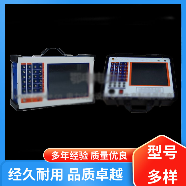
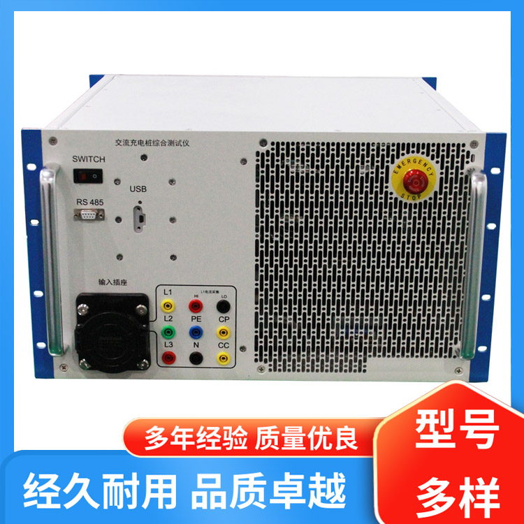
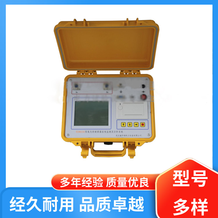
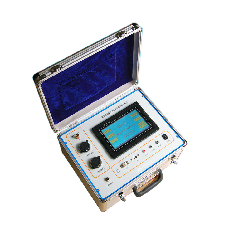
й’ҲеҜ№зӣ®еүҚеҸ‘дҫӣз”өзі»з»ҹзҡ„жЈҖдҝ®зҺ°зҠ¶пјҢжҲ‘е…¬еҸёиҮӘиЎҢејҖеҸ‘дәҶдёҖз§Қз”ЁдәҺжөӢйҮҸй«ҳеҺӢйҡ”зҰ»ејҖе…іи§ҰжҢҮеҺӢеҠӣзҡ„жҷәиғҪеһӢжөӢиҜ•д»ӘпјҢе®ғеҸӘиҰҒе°ҶжөӢиҜ•й’іжЁЎжӢҹи§ҰеӨҙзҡ„дј ж„ҹеҷЁеңЁжҜҸеҜ№и§ҰжҢҮжҺҘи§ҰдҪҚзҪ®еј ејҖдёҖдёӢпјҢе°ұиғҪжҳҫзӨәеҮәи§ҰжҢҮжӯӨж—¶зҡ„жҺҘи§ҰеҺӢеҠӣ并记еҝҶгҖӮжңүж•Ҳи§ЈеҶідәҶжөӢйҮҸи§ҰжҢҮеҺӢеҠӣзҡ„дёҖеӨ§йҡҫйўҳгҖӮ
ED0307BеһӢйҡ”зҰ»ејҖе…іи§ҰжҢҮеҺӢеҠӣжөӢиҜ•д»Әд№ҹеҸҜз”ЁдәҺйҡ”зҰ»ејҖе…іеҲ¶йҖ еҺӮеҜ№и§ҰжҢҮеҺӢеҠӣзҡ„жЈҖйӘҢпјӣж”№еҸҳеҺӢеҠӣдј ж„ҹеҷЁзҡ„еҪўзҠ¶д№ҹиғҪжөӢйҮҸж–ӯи·ҜеҷЁзҡ„и§ҰжҢҮеҺӢеҠӣгҖӮ
дәҢ.дё»иҰҒжҠҖжңҜеҸӮж•°
е·ҘдҪңзҺҜеўғпјҡ-20пҪһ40в„ғпјҢвүӨ80%RH еӨ§ж°”еҺӢеҠӣ 86пҪһ106kpa
з”өжәҗз”өеҺӢпјҡAC220VВұ10% 50HzВұ10% жҲ–жңәеҶ…й”Ӯз”өжұ еҠҹзҺҮпјҡвүӨ20 W
жөӢйҮҸиҢғеӣҙпјҡвүӨ1000 N иҜҜе·®пјҡвүӨ1пј…
жөӢйҮҸзӣҙеҫ„пјҲи§ҰжҢҮејҖи·қпјүпјҡ5.5mmпҪһ90mm еӨ§дәҺ90mmпјҲеҸҜе®ҡеҲ¶пјү
еҶ…зҪ®й”Ӯз”өжұ пјҢз”өжәҗе·ҘдҪңж—¶й—ҙпјҡвүҘ6е°Ҹж—¶пјҲеҸҜе®ҡеҲ¶пјүгҖӮ
е……з”өж–№ејҸпјҡ
a)дё“з”Ёе……з”өеҷЁжҺҘйқўжқҝй”Ӯз”өжұ е……з”өжҺҘеҸЈе……з”өпјӣ
b)йқўжқҝAC220VжҸ’еӨҙе……з”ө
дј ж„ҹеҷЁдҝЎеҸ·зәҝй•ҝеәҰпјҡ10m
з»қзјҳз”өйҳ» пјһ2MО©
д»Ӣз”өејәеәҰ з”өжәҗеҜ№жңәеЈіе·Ҙйў‘1.5KVиҖҗеҺӢ1еҲҶй’ҹпјҢж— й—Әз»ңдёҺйЈһеј§гҖӮ


www.114global.com дёӯе•ҶеЈ№еЈ№иӮҶжІіеҢ—зҪ‘з»ң科жҠҖжңүйҷҗе…¬еҸёзүҲжқғжүҖжңүВ В иҒ”зі»ең°еқҖпјҡжІіеҢ—зңҒзҹіе®¶еә„еёӮжЎҘиҘҝеҢәдёӯеұұдёңи·Ҝ118еҸ·дёңж–№ж–°дё–з•Ңдёӯеҝғ6009е®Ө е№іеҸ°жңҚеҠЎз”өиҜқпјҡ4006299930В з”өдҝЎдёҡеҠЎз»ҸиҗҘи®ёеҸҜиҜҒпјҡеҶҖB2-20240433В В еҶҖICPеӨҮ19018905еҸ·-9В В  еҶҖе…¬зҪ‘е®үеӨҮ13010402003046еҸ·