
[Summary]The main difference between the pre-paid energy supply system for enterprises and institutions and the residential pre-paid energy supply system is that the former has particularly high requirements for safety and reliability; a sudden interruption in energy supply to certain key departments can easily lead to accidents. To meet the safety and reliability requirements for energy supply in enterprises and institutions, an IC card pre-paid system has been developed. A complete pre-paid energy supply system consists of the card selling and manufacturing subsystem, energy metering subsystem, pre-paid control subsystem, pre-paid monitoring subsystem, and transmission media between the subsystems. The pre-paid control subsystem includes IC card readers, pre-paid controllers, control valves, and auxiliary equipment. The software of the card selling and manufacturing subsystem should include operator password verification (overall view), permission management, unit file management, IC card initialization, IC card recharge, and operation trace query. The pre-paid energy supply system integrates three major functions: energy metering, data collection, and energy supply control, achieving functions such as energy metering, timely data transmission, and power shutdown for non-payment. The system has been widely used in power supply areas, receiving positive feedback from users.
【Keywords】Smart Grid; Energy; Wireless Communication; Reliability; Pre-paid Systems; Data Collection; Monitoring
0 Introduction
In recent years, the rapid development of the pre-paid energy system has been of great significance to the extensive energy supply network. This system not only saves on the labor costs associated with on-site meter reading but also transitions from post-paid to pre-paid, effectively eliminating the long-standing issue of energy fee arrears, and achieving modernization in billing management. The growth of the pre-paid energy system has spurred the development of energy metering and control equipment, leading to the emergence of pre-paid water, electricity, and gas meters with pre-paid management and control functions. Consumers purchase a 1C card or recharge at the sales point, then deposit the fees into the meter, which automatically opens the valves for water or gas supply. Throughout this process, both suppliers and consumers find it convenient. While this card-based consumption presents minimal safety risks in household settings, it poses more complexity for industrial manufacturing enterprises. Particularly in industrial furnaces and chemical production processes, sudden energy supply disruptions can easily lead to accidents. This article focuses on the safety and reliability requirements of energy supply for enterprises and institutions, and introduces the development of the IC card pre-paid system.
Composition of the Energy Prepayment System
The Energy Pre-paid System consists of five basic components: card selling, card-making subsystem, energy metering subsystem, pre-paid control subsystem, pre-paid monitoring and management subsystem, and the transmission medium between the systems, as shown in Figure 1.
1.1 Card Sales and Card Production Subsystem
Card selling and card-making sub-systems are generally installed at the financial specialists' offices in the finance department or heat network management stations. The hardware includes contactless IC card readers/writers and the connected PC. The software interface includes operator password verification (general view), permission management, unit file management, IC card initialization, IC card recharge, and operation trace search, among others.
1.2 Energy Metering Subsystem
Due to the variations in energy types, medium types, and design, the composition of energy measurement subsystems also differs. For heating systems that use steam as the medium, the objects of measurement are the mass flow or heat flow of steam, and the system typically consists of flow transmitters (or sensors), pressure transmitters, temperature sensors, and flow calculators. To enhance system reliability, some designs include uninterruptible power supplies. To transmit measurement results promptly to the control room's monitoring station, flow calculators usually feature digital communication ports, with common transmission media including wired, wireless, and mobile communications (GPRS or CDMA). With the reduction in mobile communication costs, people now prefer using mobile communication methods. The structure of the steam pre-paid system using GPRS as the communication medium is shown in Figure 2.
According to standards, the accuracy of the steam flow measurement system should be ±2.5%, but the actual accuracy achieves ±1.5%. The accuracy can reach ±0.5% ±1.0% near the normal flow rate or at full-scale flow.
1.3 Pre-Paid Control Subsystem
The Pre-paid Control Subsystem consists of a pre-paid controller and control valves. The control valves are installed on the pipeline, while the controllers are equipped with card readers and are typically mounted at locations convenient for operation.
The pre-paid controller should possess the following basic functions.
①Card Reading. The pre-paid control box is equipped with a contactless card reader, which reads the amount from the 1C card purchased in advance into the single-chip microcomputer of the control box that matches the card number, and displays it on the color LCD screen. The remaining balance is adjusted accordingly.
② 1C Card Recharge Record Screen. Each time a card is swiped for recharge at the control box card reader, a recharge record is created upon successful transaction. The record includes: recharge date, time, and amount. All recharge records can be viewed by operating the controller's panel.
③ Pre-paid Main Display Screen. The main display screen is used to inform hot users of the remaining balance in the control box and the current steam unit price. It also shows the cumulative flow and the current opening degree of the control valve.
④ Auto-shut valve. The controller (or computer) automatically closes the valve when the balance reaches zero.
⑤ Fault diagnosis codes.
1.4 Data Collection and Monitoring Subsystem
The system serves as the monitoring and command center for the entire energy supply network. It first collects, stores, and processes the measurement results from energy meters distributed across various sites, creating various displays for operational management personnel to utilize. Secondly, it monitors the energy consumption and remaining balance of each customer's terminal, and automatically sends reminder SMS messages three, two, and one day in advance when the balance is low. When the remaining amount reaches zero, the on-site control valve is automatically closed by the computer or the pre-paid energy controller. The monitor station's computer screen can be quite comprehensive, typically featuring geographical distribution maps of detection control points, dynamic flow charts, dense displays of metering data, historical curve charts of metering data, trend charts of pipeline losses, comparative analysis charts, event reports, statistical reports, and billing notice creation screens, which have been described in detail in relevant literature. For monitoring operation stations with pre-paid management functionality, there should also be cost management screens and control valve operation screens.
Research on Key Issues in System Design
2.1 Reliability Issues
Safety and reliability in design are crucial for pre-paid systems.
The system does not unexpectedly shut off valves due to power failure of the main power supply or interruption of the control lines. When the main power supply is powered on or off, the electric control valve maintains its original valve position and does not shut off automatically; similarly, it will not shut off automatically after the control line is disconnected.
② The opening and closing of the host computer, as well as system debugging, should not trigger the shutdown of the control valve. Before the system is officially put into control, if the power supply to the control valve is turned off, any operation during the debugging process will not cause an unexpected shutdown of the control valve. The conditions for the host computer to operate the control valve are: the application is running normally; it can communicate normally with the lower computer; and the corresponding valve shutdown key is pressed by the on-duty staff. When the host computer is powered on, off, experiences a power outage, or encounters an error, it is impossible to meet all three conditions simultaneously, thus ensuring the system's safety.
③ Preventing the issue of control valves sticking. Most control valves in the pre-paid control system are seldom actuated, with some metering points possibly not actuated for a year. Consequently, the valve core remains stationary, which is prone to sticking due to foreign matter like scale in the fluid, preventing the valve from being closed when needed. The solution is to periodically move the valve core, such as designing a program in the supervisory control and data acquisition (SCADA) system to regularly send a signal to partially close the valve and automatically record the valve's operation.
In response to data, the computer determines whether the control valve operates normally. During the test, the degree of valve closure should not affect the user's operation. The foundation for this measure is the selection of a proportional electric control valve, equipped with proportional position feedback.
④ To prevent issues caused by the opening of the chilled water valve, it is essential to follow a specific procedure for the passage of steam through the chilled water pipes. Rapid operation can easily lead to water hammer, damaging equipment. In a pre-paid control system, the owner unit can install a bypass valve with a sufficiently small bore next to the control valve; upon starting the chilled water pipe, first open the bypass valve to heat the pipe; after the heating process is complete, then open the pre-paid control valve. After the pre-paid valve is closed, the bypass valve still provides a small amount of steam to the downstream, preventing water hammer when the pre-paid valve is reopened due to water accumulation inside the pipes.
⑤ Fault diagnosis of instruments and management of diagnostic information. The normal operation of prepayment controllers and meters is a prerequisite for the proper functioning of the prepayment system. Therefore, both prepayment controllers and flow calculators should be equipped with necessary fault diagnosis functions and upload diagnostic results to the host computer for display, alarms, and alarm record compilation. Additionally, the LCD screen of the instruments also displays diagnostic results (codes), thereby enhancing the reliability of the system.
2.2 Anti-Cheating Issues
Measurement devices used for trade transactions occasionally experience fraud incidents, with numerous methods employed. Among the existing instruments, the following anti-fraud strategies have been implemented:
Strategies to Prevent Power Disconnection Cheating: The flow calculator inside the metering box is equipped with a power outage recording function, capable of recording planned power outages and intentional power disconnections without missing a single instance. After the main power supply is disconnected, the uninterruptible power supply's charging and discharging controller sends a dry contact signal to the switch input port of the flow calculator, which is then transmitted to the host computer via the digital communication port. An alarm signal is emitted on the monitor, and an event record is made for future reference.
② Unboxing door alarm. A limit switch is installed inside the on-site instrument box. Once the box door is opened, a set of contact signals is sent to the upper computer via a calculator for alarm activation.
③ Prevent cheating by downloading data from the master station to the slave station. In a pre-paid control system, the master station needs to download data from the slave station (controller) to operate the control valves installed on-site. If the flow calculator is integrated with the controller, it may raise concerns among users: If the master station can download control valve data, why can't it also download data related to measurement? To alleviate this concern, the controller and flow calculator are separated into two separate meters. The flow calculator used for measurement is subject to verification by a government authorized institution, and upon passing the verification, it is sealed with an official stamp.
④ Prevent cheating by modifying data related to measurement results. In the intelligent traffic calculator, many data can be modified after entering the password. To prevent unauthorized modification of these data by those who possess the password, a "Key Data Modification Record Function" is set up in the traffic calculator after the instrument is manufactured. Each modification of key data will generate a record with yellow ink, thereby eliminating this cheating method.
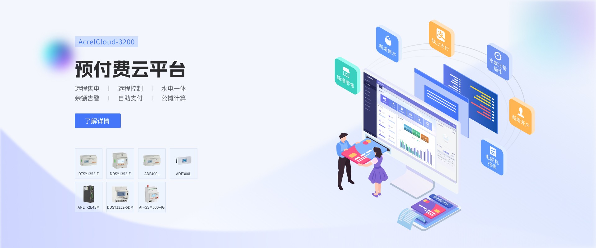
3 Acrel Acrelcloud-3200 Pre-Paid Utility Cloud Platform
3.1 Overview
The AcrelCloud-3200 Pre-Paid Electricity and Water Cloud Platform is a sales management system developed by Ankerui Company, designed to be paired with the DDSY-1352 Single-Phase Electronic Pre-Paid Energy Meter and the DTSY-1352 Three-Phase Electronic Pre-Paid Energy Meter. Additionally, it can be optionally equipped with a remote transmission valve-controlled water meter to form an integrated pre-paid electricity and water system, achieving the goal of paying before using water, with the valve automatically closing when the remaining water is depleted. It primarily handles the parameter settings for energy meters/water meters, merchant electricity/water sales management, and energy consumption management. The system is easy to operate, enabling property management companies to remotely monitor and control in real-time, featuring a user-friendly interface and effective data statistics and management. It is easy to install and is an ideal product for electricity and water management departments, commercial plazas, and property communities to improve electricity and water management levels and solve the difficult issue of billing.
3.2 Application Venue
This platform is suitable for apartment renters, shopping malls, apartment hotels, property communities, office buildings, logistics warehouses, universities, chain supermarkets, smart parks, and farmers' markets, among other locations.
3.3 System Structure
3.4 System Features
3.4.1 Room Surveillance
Elegantly display all room status information, including the building and floor, online disconnection status, and billing status. Accessing room details allows for real-time monitoring of current information and insights into daily electricity consumption and usage costs. Various remote control operations for the in-room electricity meters are available, such as account opening, electricity price settings, power sales, returns, alarm amount settings, and switch operations.
3.4.2 Electric Meter Activation
The system supports both individual metering and multiple meters under one account for store registration; it allows for customized electricity pricing plans such as single rate, peak/off-peak pricing, and tiered pricing; it enables pre-setting registration information for one-click registration later; it supports setting default three-level alert for total meter amount, with customizable alert amounts and frequency; push notification methods include SMS, APP notifications, email, voice calls, and WeChat official account push.
3.4.3 Charging and Payment
Remote top-ups are available for meters that have already been activated, with electricity charges being issued to the meters in real-time. The meters deduct electricity fees based on real-time kilowatt-hour readings, and the system also supports early billing, with the amount being transferred to the system account quickly and stably.
3.4.4 Financial Management
Order Overview includes all records of water and electricity top-up refunds in the system, as well as property fee deduction statements. Revenue Summary allows for the calculation of water and electricity income, along with income composition, across daily, monthly, annual, and other time spans.
3.4.5 Report
The system also offers multiple reports for inquiry. The Comprehensive Power Consumption Report assists in financial statistics by tracking the total power consumption of shops each month, peak and off-peak power consumption, electricity bills, and year-on-year energy consumption analysis, which can compare the energy consumption gap between each month and the same period last year. The Daily, Monthly, and Annual Energy Consumption Report allows for inquiries into the energy consumption of each stage of the meter from three different dimensions: daily, monthly, and annual.
3.4.6 Batch Operations
To facilitate the management and configuration of a large number of meters, users can create batch operation tasks within the system, such as setting electricity prices, meter controls, instrument configurations, and recharging. These batch tasks can be executed immediately or scheduled for later.
3.4.7 Custom Pricing Plans
To accommodate a variety of user billing needs, such as property fees, rent, and service charges, the system supports user-defined billing items. Billing methods can be set to directly deduct from the account or generate reminder invoices. They can be configured for periodic or one-time payments, and can charge either a fixed amount or based on room square footage, among other options.
3.4.8 Allocation of Electricity Consumption in Public Areas
Design a primary table and then allocate associated sub-tables. The system automatically converts the electricity usage from the primary table into electricity costs on a monthly basis, which are then deducted from the sub-tables, eliminating the need for manual calculations. There are various ways to allocate costs, such as by proportion, room area, or consumption. Charging methods include direct deduction or generating maintenance billing statements.
3.4.9 WeChat Official Account Online Payment
Customers can self-inquire about their electricity meter usage and make payments through WeChat Mini Program or official WeChat account.
3.5 System Hardware Configuration


4 Closing Remarks
The pre-paid energy system integrates three major functions: energy measurement, data collection, and energy supply control, achieving features such as energy measurement, timely data transmission, and power cutoff for non-payment. The use of 1C cards effectively prevents gas theft, ensures fair and just measurement, and significantly reduces the cost of manual meter reading. The system employs some intelligent methods to ensure that users do not experience unexpected power outages, safeguarding safe gas usage. The system has been widely used in the power supply area and has received positive feedback from users.
Reference
Ji Guan. Common Methods for Steam Flow Measurement[J]. World Instrumentation and Automation, 2009(1): 33-37.
[2] Yu Yang, Ji Gang, Xu Huajia. Application of GILFLO Flow Meters in Steam Flow Measurement [J]. Shanghai Measurement & Testing, 2008(2): 19-22.
Ji Gouang, Cai Wuwu. Flow Calculator [J]. Automation Instrument, 2000, 21(9): 20-25.
Han Peng, Zhou Yuan, He Zhijun, Ji Bo Feng, Ji Gang. Energy Supply Prepayment System for Energy-Consuming Units[J]. Automation Instrumentation, 2017(2): 93-95
[5] Ankorree Enterprise Microgrid Design and Application Manual, 2022.05 Edition.