

I. Preface
This instrument is widely used for leak detection in bag dust removal systems in metallurgy, electricity, chemical industry, food processing, etc. When used for leak detection in dry desulphurization systems of large-scale thermal power generating units, it can prevent wear on the vacuum fan caused by the破裂 of the bag filter in the dust removal system, as well as prevent excessive dust emissions and air pollution due to bag breaches in the positive pressure dust removal and powder separation process. Particularly in the metallurgical iron-making process, where the bag dust removal system for blast furnace gas, which is highly toxic (CO content approaching 30%) and operates under positive pressure, has special practical value. Over the past decade, from small to large furnaces (up to 2500M³) and from single installations to multiple installations (some manufacturers have installed several), this instrument has undergone production tests across various manufacturers in China. It features sensitive response, reliable operation, minimal maintenance requirements, and strong practicality, meeting production needs and being capable of replacing manual leak detection. It can also display concentrations in real-time, making it a domestic innovation with significant economic, social, and environmental benefits, and holds great potential for widespread use.
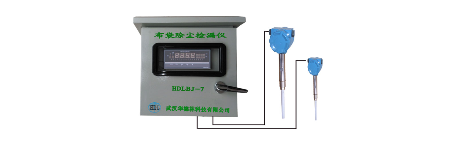
The HDLBJ-7 Bag Filter Leak Detector features two series. One series allows a single instrument to simultaneously monitor the operating conditions of 8 or 10 bag filter dust collectors online. This series of instruments includes computerized patrol inspection, overload indicator lights, sound alarms, as well as 4-20mA analog current indication and switch quantity output. The other series not only monitors the operating conditions of the dust collector boxes online but also is equipped with a total duct concentration meter, enabling real-time monitoring of dust concentration in the main duct. The instruments in this series display the dust concentration values of each bag filter dust collector box and the main duct on an LCD screen, and have dust overload alarms and sensor fault alarms. Additionally, they can output 4-20mA current, RS485 interface, and switch quantity output (passive).
The HDLBJ-7 series instruments feature a simple structure, high sensitivity, accurate and timely signals, safe and reliable operation, easy installation, minimal maintenance, and a wide range of applications, making them a highly practical dust online monitoring device for various industrial enterprises.
II. Equipment List Description and Key Technical Specifications
Name Praise | Type No content provided for translation. | Technical Update: Our company is proud to announce a significant upgrade to our product line, enhancing performance and user experience. Art Please provide the Chinese content to be translated. No Chinese content provided. Please provide the text to be translated. | Installation Location | |
Baghouse Leak Detection Sensor | WKD-6-300 model | Insertion Depth:L=300mm Sensor-Integrated Mount Base | Various Bagged Liquefied Natural Gas (LNG) Exports | |
Executive Dust Concentration Monitoring Sensor | WKD-6-800 Model | Insertion Depth:L=800mm Sensor-Installed Base Mount | Total Clean Natural Gas Export Pipeline | |
Signal Processing DeviceTransmitter Enclosure | HDLBJ-11 Model | Number of Test Points11 AM (optional) 10 Gas Bag Export Leak Checks Output4-20mA signal or switch signal (bag break alarm) Power Supply:AC220V Signal InPLC System | Electrical Room of the Hot Blast Furnace (or the power distribution room near the blast furnace) | |
Signal Transmission Cable | RVVSP-2 | |||
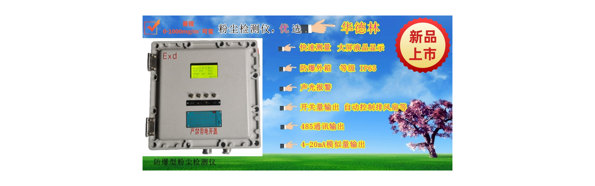
Measurement Range | Dust Concentration | 0-1000mg/m3 | ||
Pipe Diameter Under Test | 0.1- 4.0m | |||
Particle size tested | 1-80μm | |||
Work Conditions | Sensor measurement points enable temperature | <400℃ | ||
Sensor Measurement Point Pressure Range | 2.0Mpa | |||
Sensor insertion depth | 300mm (with a total main pipe diameter of 800mm) | |||
Instrument operating environmental temperature | -20℃-80℃ | |||
Relative humidity of the sensor operating environment | <90% | |||
Cable length between sensors and transmitters not to exceed1,000 meters | ||||
No content provided for translation. No Chinese content provided. | Alarm Delay Time | Adjustable from 0 to 20 seconds | ||
Adjustable input signal sensitivity | ||||
Direct Current | 4~20mA | |||
Change Please provide the Chinese content to be translated. No Chinese content provided. Machine Box | Transmitter enclosure dimensions: width, height, and thickness | 430×530×200㎜ | ||
Section 3: Working Principle and Process (Taking the HDLBJ-7 Model as an Example)
In flowing powdered materials, particles collide with each other and with the tube walls or filter bags, generating static charges due to friction and impact. This creates a static field, whose variations reflect the change in dust content. Leak detectors measure these changes in the static field to determine if the filter bag dust collection system is operating properly. When a filter bag is ruptured, the dust content in the gas-solid two-phase flow within the pipeline increases, along with an enhanced static field intensity.
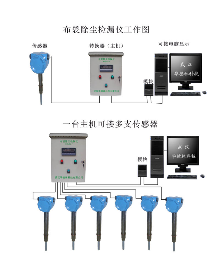
This system is primarily composed of three parts: ① sensors (signal collection section), ② transmitters (signal processing section), and ③ signal transmission. The block diagram of its principle is shown in Figure 1, and the function of each point and the arrangement of buttons on the panel are depicted in Figure 2.
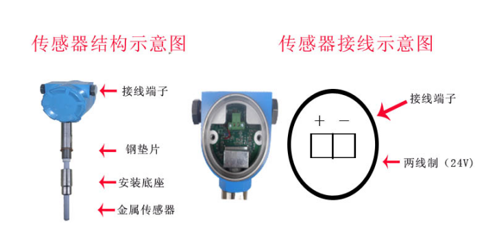
The role of the sensor is to convert the static field formed during the flow of powders into an electrical signal by means of electrostatic induction, which is then transmitted to the transmitter via a coaxial cable.
The transmitter is composed of a multi-channel board, with its output being an analog current and a photoacoustic display that varies with the measured powder content. The new meter outputs a 4-20mA current signal, alarm switch quantities, or data signals via the RS485 interface.
During normal operation (i.e., without bag breaches and within permissible powder content levels), the HDLBJ-7 model displays all green lights illuminated and red lights extinguished, while outputting analog current values. The current values output by each channel are measured through automatic patrol and manual point selection, both composed of a single-chip microcontroller. The device can operate in either "Automatic Patrol" or "Manual Point Selection" modes as required. The "Box Selection" button serves as both a switch to toggle between "Automatic" and "Manual" modes and as a switch to switch between box measurements when in manual mode.
IV. Installation and Precautions
Sensor installation
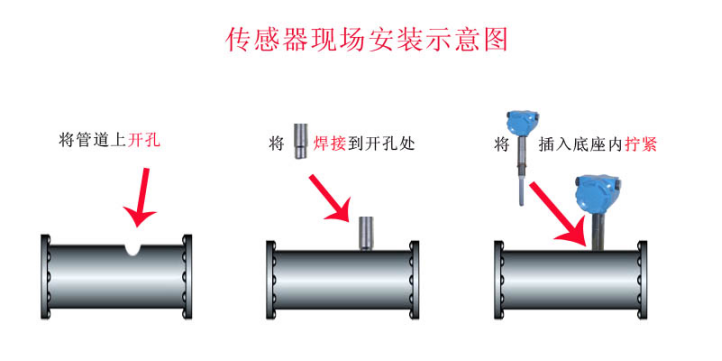
① Sensors should be installed on vertical pipes, more than 5 times the diameter of the valve or elbow. When sampling from horizontal pipes, they should not be installed at the bottom. For a gas dedusting system with multiple chambers operating in parallel, a hole (with a diameter of φ25mm) should be drilled on the pipe before entering the main clean gas pipeline at the outlet of the tested dedusting chamber. The fixed sensor's plug-in interface should be vertically welded to the top of the longer horizontal pipe section.
② The length of the sensor probe is selected and supplied as a set by the instrument manufacturer based on the pipe diameter to be measured by the user. The base should be flush with or extend beyond the inner wall of the pipe, matching the end of the insulating sleeve of the sensor probe. The socket is supplied as a set by the instrument manufacturer.
③ A purple copper pad is added between the sensor and the base, connected and tightened with a screw thread to prevent the leakage of toxic gases inside the pipe.
The sensor junction box is rainproof, directly secured to the sensor probe with wire clips, and sealed with an O-ring rubber pad. The outgoing wire is tightly connected to a half-meter-long sheathed metal hose via a metal flexible tube connector. The other end of the hose is connected to a metal cable conduit, secured and sealed with plastic tape to prevent rainwater from渗入the conduit. The flexible metal tube must have a support point to prevent swinging in the wind and rain, which could introduce static interference signals.
2. Installation of Monitoring Devices (Installation of Secondary Instruments)
The monitoring device should be installed on the instrument panel in the control room near the sampling point, supported and secured by brackets, and the device should be as far away from strong magnetic fields as possible.
For users with a noisy control room environment, to make the alarm sound louder, the internal alarm horn of the device can be extended outside and mounted on the instrument or connected to a louder external speaker (there is an external speaker terminal on the back of the instrument).
3. Cable and System Installation:
Sensors must be connected to alarm devices using shielded cables. Standard cables cannot be used as substitutes.
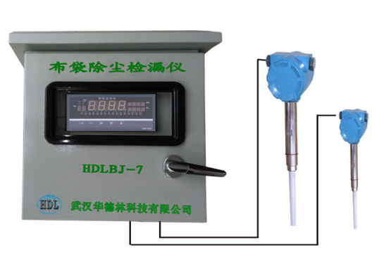
HDLBJ-7 Type Baghouse Dust Collector Online Monitor
Color LCD Display Screen

Note: 1. The bar graphs indicate the dust content of each box, with units of mg/m³.
2. The sensor fault alarm bar graph heightens, changing from green to pink.
3. Bag break alarm bar graph increases; if dust exceeds 10mg, the bar graph turns red.
Section 6: Static and On-site Operation and Commissioning
Pre-Debugging Inspection
(1) Inspect the distribution isolators across all channels to ensure they are functioning properly. When normal, the distribution isolator's green light should be on, and the red light should be off. If the red light is illuminated, it indicates a fault with the on-site sensor or a broken wire in this channel. Please check it.
(2) Verify that the box numbers correspond to the cable numbers and the secondary instrument sequence numbers, and make clear markings on the cable heads on the side of the table.
Check for any short-circuiting in the signal transmission cables, ensure the conduit is securely fastened, and verify that all connections are properly sealed.
After all inspections are completed, the on-site trial operation and debugging can proceed.
Static Debugging of the HDLBJ-7 Bag Filter Leak Detector
Static debugging of the secondary table, start debugging after preheating for half an hour upon power connection.
Secondary calibration adjustment: Performed without an input signal, shifting the instrument from automatic to manual mode.
Adjust the sensitivity to a low value (turn the "sensitivity potentiometer" clockwise, monitor the output terminal with a multimeter).
(1) Zero Adjustment: After the field transmitter is installed on the pipeline, the field indicator should display 0 or within a 5% deviation. If not, turn the "Zero Adjustment Potentiometer" to display the correct value.
(2) Sensitivity Adjustment: Under low input signals, if the instrument responds sluggishly, you should fine-tune this potentiometer at this time.
(3) Adjustment of Fullness: The item is pre-adjusted at the factory; no on-site adjustment is required. If an adjustment is indeed necessary, please contact the manufacturer.
3. On-site operation and debugging
On-site debugging shall be conducted under normal operation of the production system without any torn bags.
1. Turn on the power switch, and the instrument enters the automatic inspection mode. Typically, after a 30-minute preheat, connect the input signal terminals of each enclosure to the instrument. At this point, the inspection instrument sequentially displays the dust concentration values of each channel.
2. Set the range values for each channel of the patrol instrument and the alarm data. Based on the empirical values, set the dust concentration at the time of bag rupture as the current alarm threshold. This can also be changed according to the site requirements in the future.
During normal operation, the indicator lights on all channels are green, indicating low concentration levels that are relatively close. If there is a breach in the bag, the concentration value will significantly increase, causing the red light to illuminate and triggering an alarm signal for a breach.
After adjusting the sensitivity of all cabinets, switch the "Cabinet Selection" button to automatic inspection mode, and you can view the corresponding dust concentration values point by point. This indicates that the manual and automatic operations of the device are all functioning properly, the adjustment is complete, and it is ready for operation.
Section 7: Routine Maintenance and Fault Handling
After the instrument is put into operation, regular observation and maintenance should be conducted.
Monitor the automatic working status:
Monitor the digital window of the observation channel; it blinks every 2 seconds, flashing a total of 12 times before increasing the number in sequence until it reaches 12, then restarting from 1 in a continuous cycle. While observing the digital changes, the concentration indicators at each point should be close together, indicating that the automatic mode is functioning normally.
Observe the manual work status:
Press the "Case Selection" button to switch to manual mode. The digital display should not flicker, and each press of the "Case Selection" button should increment the digit by one. At the same time, observe the concentration indicator value, which should be close, indicating that the manual mode is working normally.
Regardless of being in "Automatic" or "Manual" mode, all checkpoints should display a green light and a red light should be off, without any alarm when no bag breakage occurs. If the indicated value exceeds the alarm setting, investigate with the cloth bag operation staff to determine if there is any abnormal system condition. Check for any damaged cloth bags.
2. Sensors are inspected during the blast furnace overhaul
During each quarter's blast furnace maintenance, the sensors are removed to check for any dust bridging and to perform cleaning.
When a drum bag punctures or exceeds the dust content, the corresponding red light does not illuminate, or the bar graph does not turn red.
Inspect whether the core wire solder joints at the junction box cable and secondary meter input are loose or detached; re-soldering can eliminate the issue.
② The sensitivity of the channel for the dust collector's housing was set too low. When the bags are not severely damaged, the concentration value does not rise significantly, failing to reach the alarm level, resulting in the red light not illuminating and no sound alarm. Adjusting the sensitivity higher can resolve this issue.
If the cable connection to the probe rod is disconnected, the red light will turn off or the rod diagram will turn green, indicating that the fault is with the probe rod. This is often due to dust accumulation adhering to the probe rod. By removing the probe rod and cleaning off the dust, the fault can be eliminated.
