

Certainly, here's the translation: You probably have a general understanding of acoustic measuring pipes. Today, the editor from an acoustic measuring pipe manufacturer shares what an acoustic measuring pipe is and its working principle. An acoustic measuring pipe is made by professionally forming cold-rolled steel pipes.
Starting from the bottom of the acoustic probe, as it ascends along the entire length of the pile, the speed of sound propagation within it is within a certain range. Factors such as fractures, cracks, mud inclusion, and poor density will cause the sound wave to attenuate, resulting in an extended propagation time, thereby increasing the sound time and decreasing the calculated sound velocity, including the influence of the acoustic probe on the detection.
In the acoustic tube testing, the principle primarily used is the ultrasonic penetration method. The tube itself serves as a channel for the ultrasonic detection probe to smoothly enter the interior of the pile foundation.
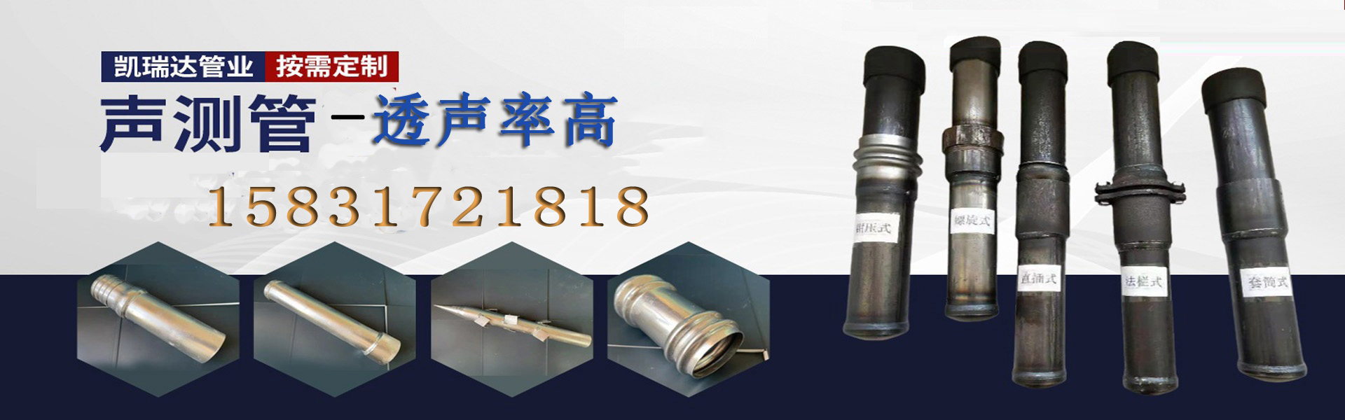
During the inspection, insert the end of the ultrasonic test tube into the socket end until it reaches the marked line. Use a hydraulic clamp to simultaneously compress the side section of the U-shaped groove. Both the socket end and the receiving end of the tube material at the clamping section undergo simultaneous contraction and deformation (forming a hexagonal shape), which serves to locate and secure, resist pulling out, and resist rotation. This effectively achieves the connection of the ultrasonic test tube.
Principle of Ultrasonic Wave Transmission Method for Detection
The basic principle of the ultrasonic pulse velocity method for detecting the integrity of pile bodies is: by exciting and receiving high-frequency elastic pulse waves between the pre-installed acoustic measurement pipes within the pile body, it is determined whether the concrete piles are properly set and whether there are any broken piles!
The ultrasonic testing device for the sound wave transmission method includes an ultrasonic detector, ultrasonic transducer (also known as a probe), pre-buried measuring pipes, and also features a transducer elevation control winch and a data processing computer. According to the principle, the measuring pipes should possess certain strength, toughness, and stiffness. Generally, steel pipes with good adhesion to concrete and a high sound transmission rate are used, with an inner diameter of 43-60mm, and threaded connections are recommended for the joints. The sound measuring pipes should be welded or tied to the inside of the reinforcing cage and buried to the bottom of the pile. The pipe opening should be more than 300mm above the detection work surface to ensure the unobstructed flow of the sound measuring pipe and the integrity of the pipe wall. The sound measuring pipes should be kept parallel to each other, and the spacing should be maintained relatively uniform.
The following testing requirements should be met.
When the diameter D is less than or equal to 1000mm, it is recommended to install two acoustic measurement pipes.
When the diameter is between 1000 and 2000mm, it is advisable to install 3 acoustic measurement pipes.
When D is greater than 2000mm, it is advisable to install 4 acoustic survey pipes.
D represents the pile diameter of the inspected pile design.
During routine inspections, the following quality issues may occur with sound testing pipes:
1. Foundation bottom sound testing pipe bending
Due to improper construction, the sound velocity curve is abnormal, which may likely result in misjudgments or misinterpretations.
Two piles have shown tilt or deformation of the sound wave testing pipes.
Improperly secured or excessively spaced acoustic pipe bindings can lead to the pipes being squeezed by concrete, resulting in tilting or bending deformation. This can cause the distance between pipes to increase or decrease, and even render it impossible to categorize the integrity of the pile body. Consequently, only methods such as core drilling or other reliable techniques can be employed for detection.
Excessively long casing at the 3 sound testing pipe connection
Due to the excessive length of the steel casing, the air sealed inside cannot be released.
4 Sound Testing Tube, Diameter Too Large
A general assumption is that the transducer is located at the center of the acoustic tube, which increases the delay of the coupling water layer.

