


液化天然气储罐厂家:
液化天然气储罐生产厂家:Heze Boiler Factory Co., Ltd.
I. LNG Tank Safe Operating Procedures
1.1.1 Storage Tank Operation Process Specifications
1)Highest AllowableWork Pressure: 0.86MPa
2)DesignTemperature: -196℃
1.1.2 Tank Inflow Procedure
1.1.2.1 Preparations
1) Operator Requirements: Operators must hold valid certificates after undergoing safety education and technical training for operation. They are required to wear necessary protective gear and work uniforms during their duties.
2) Pressure Testing Requirements
3) All equipment should undergo pressure tests in accordance with design requirements prior to operation.
4) The test pressure gas should be dry nitrogen, with oxygen content not exceeding 3%, moisture dew point not exceeding -25°C, and free of oil contamination.
5) Bleed-off Replacement Requirements: Bleed-off replacement is a safety measure to ensure the safe filling of equipment with liquid. It should be pre-bleeded with nitrogen containing no more than 3% oxygen, ensuring no oil contamination and a dew point of no more than -25°C. Subsequently, replace with LNG to achieve the required liquid purity before allowing the liquid to be filled.
6) Pre-cooling: After pressure testing passes, pre-cooling with liquid nitrogen is required to ensure the reliability of the equipment's low-temperature operation: The storage tank must be purged and pre-cooled with nitrogen before first use. The high purge pressure should be equivalent to 50% of the high working pressure, or less than this pressure.
1.1.2.2 Initial Liquid Filling Operation of Storage Tank
1) Open both the upper and lower liquid inlet valves simultaneously for filling. Simultaneously, open the overflow valve of the liquid to release the gas inside the storage tank. Continue until LNG gas is discharged, then immediately close the overflow valve.
2) When the tank is filled to more than 50% of its volume, the lower liquid inlet valve should be closed.
3) Upon reaching 85% of the tank's capacity, close the liquid inlet valve and stop filling for 5 minutes to allow the liquid level to settle. Then, reopen the liquid inlet valve and continue filling until liquid starts to overflow from the full overflow valve. Immediately close the full overflow valve, halt the filling process, and shut off the liquid inlet valve.
4) Upon initiating fluid filling, loosen the connectors at both ends of the level gauge, fully open the liquid phase valve and the gas phase valve for level display, and check if there is any moisture in the exhaust gas flow. If moisture is detected, continue to exhaust until no moisture is present. Then, tighten the connectors at both ends of the level gauge and close the balance valve to ensure the level gauge is in normal operating condition.
1.1.2.3 Filling Tank Procedure
1) Upon the first formal filling, the gas phase pressure inside the tank should be as low as possible during subsequent refills.
2) Fill both top and bottom simultaneously. When the level gauge indicates approximately 50% full, close the lower liquid inlet valve. When filled to 85% of the tank's capacity, close the upper liquid inlet valve and stop filling for 5 minutes to allow the liquid level to settle within the drum. Then, reopen the upper liquid inlet valve and continue filling until liquid starts to discharge from the overflow valve. Close the overflow valve and simultaneously close the upper liquid inlet valve to stop filling.
3) Observe the pressure gauge and level gauge during filling. (If the pressure rises above the filling transfer pressure or nears the safety valve pressure, it is necessary to open the gas vent valve to release an appropriate amount of vapor from the storage tank.)
4) Fill out the operation record form
2. Tank Pressure Boosting Operation Procedure
1) The boost system is the pressure regulating system for the storage tank. When the tank pressure falls below the set value, we open the boost regulating valve to increase the pressure in the tank.
2) During operation, open the boost liquid phase valve to allow LNG to enter the boost gasifier directly. After vaporization, it passes through BOG into the storage tank. At this point, closely monitor the pressure and close the boost liquid phase valve once the storage tank pressure reaches the desired level.
3) Cautionary Notes:
a) During operation, the LNG tank must maintain a liquid level of ≥15%.
b) During the operation of the boost system, personnel are strictly prohibited from leaving the site.
c) When the boost system is in operation, the pressure-reducing system should be in the off state.
3. Tank Discharge Operation Procedure
Preparation:
1) Check that the tank's pressure gauge, level gauge, thermometer, flammable gas detector, and safety valve are all operating normally.
2) Check if the pipeline valves, pressure gauges, and safety valves are in normal working condition.
3) Prepare all explosion-proof tools and wear protective gear.
Section 2: Gasifier Safe Operation Procedures
1) First, close the in-liquid and out-liquid valves in the system, then slowly open the in-liquid valve. When frost appears on the pipe, gradually open the exhaust valve until the required vaporization amount is reached, then stabilize the valve opening.
If frost is found on the exhaust pipe, causing the exhaust temperature to be too low, it indicates that the incoming liquid volume is too great. It is necessary to immediately reduce the incoming liquid valve to prevent overflow, and to promptly clear the frost outside the pipe, increase ventilation equipment, or take other corresponding measures.
3) The vaporizer must be oil-free. When operating, wear oil-free insulated gloves. If the vaporizer is confirmed to be contaminated with oil, the heat exchanger should be cleaned. It can be washed with hot water at 60-80°C, and if necessary, nitrogen heated to 80-100°C should be used for blowing, until it is confirmed oil-free and dried.
4) In severe cases, use carbon tetrachloride for cleaning. Be vigilant during cleaning and wear a gas mask if the odor is intense. After the chemical wash, rinse with oil-free and debris-free clean water until no chemical residue is present. Then, dry with nitrogen heated to 80-100°C until completely dry.
5) Conduct semi-annual leak inspections for the vaporizer and all pipeline systems, and maintain records accordingly.

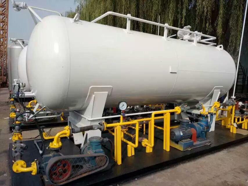
Liquefied Natural Gas (LNG) Storage Tank
LNG storage tanks are specialized products for storing liquefied petroleum gas, classified as special equipment and category III pressure vessels. They are made from 06Ni9DR material, and undergo ultrasonic testing, hydrostatic and pneumatic testing, on-site inspection by the Technical Supervision Bureau, and issuance of pressure vessel inspection certificates. The manufacturing process includes external rust removal and painting, etc. The storage tanks undergo strict quality assessment for the material, dimensions, and weld quality of the pressure components, operational quality, installation quality, internal equipment, and safety accessories.
Routine physical and chemical tests for the drum material, such as mechanical properties and chemical composition.
Strictly inspect the welding joints, seams, tank end caps, and the mutual geometric positions of all pressure elements through X-ray non-destructive testing and magnetic particle inspection. Test the product's sealing, pressure resistance, and all technical indicators that could affect the safe operation of the product.
Common LNG storage tank structures include: vertical LNG tanks, horizontal LNG tanks, vertical mother-daughter tanks, and atmospheric storage tanks.
Vertical LNG Storage Tank
Volume options include 50, 100, 150, and 200 cubic units.
Horizontal LNG Storage Tank
Volume options: 50 cubic and 100 cubic.
Vertical mother and son tanks
Sub-warehouses refer to multiple sub-containers connected in series to form an inner container, designed to meet large capacity storage needs. Multiple sub-containers are assembled side by side within a large outer container. The number of sub-containers typically ranges from 3 to 7, usually not exceeding 12. The volume of individual sub-containers should not be too large, usually between 100 to 150 cubic units, with the maximum reaching 250 cubic units. Common sizes include 1000 cubic units, 1750 cubic units, and 2000 cubic units.
Atmospheric Storage Tank:
We offer medium to large-sized atmospheric LNG storage tanks, as well as extra-large atmospheric LNG storage tanks.
2. Cautionary Notes
1. Cylinders must be stored in well-ventilated areas, maintaining a distance of at least 1.5 meters from any fire or heat source. Cylinders are strictly prohibited from being heated with fire, scalded with boiling water, or exposed to direct sunlight. Regular inspections of cylinder valves and pipeline joints for airtightness are required to ensure no leaks. Leaks can be checked using soap water, and it is strictly forbidden to test for leaks with an open flame.
2. When lighting, ignite the primer first, followed by opening the gas; do not reverse the order. There should be someone watching over it during use; do not leave it unattended to prevent boiling water from overflowing and extinguishing the flame, which could cause the escaping liquefied gas to ignite and explode. After use, the valve must be tightly closed to prevent gas leakage.
3. The liquefied gas in the cylinder should not be completely exhausted; a certain residual pressure should be maintained. The residual pressure should generally be greater than 49.03 kPa (i.e., 0.5 kg/cm², gauge pressure) to prevent air from entering the cylinder. After the liquefied petroleum gas is used up, the remaining residue in the cylinder is also a flammable substance; it must not be poured out arbitrarily to prevent fires caused by the leakage and evaporation of the residue.
4. LPG cylinders are pressurized containers that require proper maintenance and regular inspections. Prevent the cylinders from falling or being struck during handling and use. Do not use metal tools to敲击 open the valve. Protect them from direct sunlight and prolonged exposure to rain. Cylinders should be inspected every 2 years.
5. Although the explosive range of liquefied petroleum gas (LPG) is not very wide, its lower limit is small, making it easy to ignite and explode upon leakage. Additionally, since LPG is heavier than air, it tends to flow downward when leaked into the air, accumulating in low-lying areas and posing a hidden danger of gas explosions. Therefore, areas where gas is prone to leak require more than just window ventilation; attention must be given to lower-level ventilation as well.
6. When liquid gas leakage is detected indoors, windows and doors should be promptly opened for ventilation, allowing it to disperse in the direction away from any open flame. Fire is strictly prohibited in the vicinity. The area should only be used after the fault is rectified and the distinctive odor has dissipated. Any waste liquid on the ground should be covered with sand and soil before being removed to a safe location. In case of a gas cylinder fire, immediately close the valve, move it to an open area outside, and extinguish it using dry powder extinguishers, carbon dioxide extinguishers, or by covering with a wet sack.
7. Educate children not to play with cylinders carelessly, and users must understand the safety knowledge of cylinder use.
The rise of LNG community gasification in China
If the 1980s to 1990s were the era of LPG community gasification in China, then the first 10 to 20 years of the 21st century will be the era of LNG community gasification in China. The origin of LPG community gasification in China is in Shenzhen, Guangdong, and the origin of LNG community gasification should be in Zibo, Shandong. The gas source for Guangdong's LPG community gasification mainly relies on overseas imports, while the current gas source for Shandong's LNG community gasification mainly comes from the LNG production plant in Puyang, Henan. In the future, there will be more gas supply routes.
Yangzhai LNG Community Gasification Station, Zibo City, Shandong Province
This project is the first in China to design a liquefied natural gas (LNG) unloading, storage, and gasification station. LNG is transported from the Zhongyuan Oilfield to the Zibo Gasification Station in low-temperature tank trucks.
The Zibo project commenced design in June 1999 and was completed in January 2000. Zibo Gas Company started construction in January 2000, completed the construction in October 2000, and began trial operation with LNG. It officially began supplying LNG gas on December 2, 2001. It is the first liquefied natural gas (LNG) gasification station in China and the largest in Asia. The natural gas is supplied exclusively to industrial users, with a designed capacity of 120,000 Nm3/d.
Qingdao Jiaojialing LNG Community Gasification Station
The Jiajialing project commenced design in June 2000 and was completed in January 2001; the Qingdao Gas Company began construction in January 2001, and the facility was completed and successfully trial-operated in February 2002. It is the first civil liquefied natural gas gasification station in China, with a design capacity of 20,000 Nm3/d.
Guangdong Longchuan LNG Community Gasification Station Project
The Longchuan LNG liquefaction plant has a short design and construction period, taking less than a year from design to completion. The grand opening ceremony was held on May 23rd this year. The design capacity is 10,000 Nm3/d.
Although Longchuan Station's LNG currently comes from Puyang, Henan, the operator's gaze is fixed on Shenzhen. Once the Shenzhen LNG receiving station is completed, Longchuan will be the受益者.
The Longchuan LNG Gasification Plant project is a management general contracting project managed by Qingdao Chemical Engineering Design Institute.
In China, currently under construction and set to be operational are LNG liquefaction stations in Shangqiu, Henan; Jiangyan and Shuyang, Jiangsu; Fangzi, Shandong; Suzhou, Zhejiang; Miyun, Beijing; and Bengbu, Anhui. Planned and in the design phase are cities such as Yuyao, Zhejiang; Jiujiang, Jiangxi; Weifang, Shandong; Pingdu and Qingzhou; and Xiamen, Fujian. It is said that after completing the construction of the LNG liquefaction station in Longchuan, Guangdong, Shanghai Tongda Energy Co., Ltd. plans to invest in and build LNG community liquefaction stations in cities like Yangjiang, Huiedong, and Shanwei in Guangdong.
It appears that the recent LNG community gasification boom in Shandong, China, far exceeds the initial LPG community gasification surge in Guangdong. It's even faster than Japan's development pace in the 1970s. Whether it's the scale of construction, speed, or the organizational form of construction, as well as the level of public concern and its impact, it is unparalleled by the Guangdong LPG community gasification.
Section II: The global natural gas conversion project is bound to arrive.
With the advancement of the times, the development of social economy, and the demands for environmental protection, the drawbacks of coal-to-gas conversion are increasingly being exposed comprehensively. Advanced countries have successively phased out coal-to-gas conversion in the 1950s, 1960s, 1970s, 1980s, and 1990s. Petroleum-to-gas conversion also has numerous insurmountable shortcomings. LPG will become a transitional energy source as oil reserves deplete in the future. The global shift to natural gas, replacing all other energy sources, will become an inevitable development in the revolution of gas energy.
Partial Natural Gas Conversion Schedule for Some Countries
Country
During the transition to natural gas (year)
Gas Source
USA
1945-1958
Pipeline natural gas predominant
Former Soviet Union
1948-1960
Pipeline natural gas predominant
United Kingdom
1964-1977
Initially utilize LNG, later transition to pipeline natural gas primarily.
France
1962-1982
LNG and pipeline natural gas combined
Germany
1960-1970
Pipeline natural gas as the main source, with a small amount of LNG
Australia
1976-1986
Pipeline Natural Gas
Japan
1969-1998
All LNG supply
天然气的利用途径可采取管道输送和液化后用船运输、公路槽车和铁路槽车运输多种途径来实现。长输管道输送受到铺设管道需要穿过崇山峻岭、农田村庄以及征用村镇土地赔偿费用等限制,超过一定长距离,从经济角度来考虑是很不合算的。而将天然气液化后用大船(13.5万立方米)通过海上运输,送至城市边沿建设的LNG接收基地是非常经济合算的事。LNG在美国、欧洲、日本早就得到广泛的应用,而日本是世界上使用LNG最成功的国家,年用量达到了5000万吨,占世界LNG贸易量8000万吨的62.5%。亚洲的日本、韩国和台湾地区LNG消费数量,占了世界总消费量的四分之三还多。
The launch of the 3 million tons LNG project in Guangdong, China, the construction of the 2 million tons LNG project in Fujian, and the commissioning of the LNG project in India, along with the completion of the Dongding LNG receiving base in Taiwan, will lead to a significant increase in Asia's LNG demand.
Section 3: Development of the Global LNG Industry
The main component of natural gas is methane, a permanent gas that cannot be liquefied by compression at room temperature; it can only become liquid at very low temperatures (-162 degrees). Since the 1920s, with the rapid development of cryogenic industrial technology, the liquefaction of large quantities of natural gas has become possible.
In 1910, the United States began industrial-scale natural gas liquefaction. In 1917, Cabot received the first U.S. patent related to natural gas liquefaction, storage, and transportation. The same year, the world's first liquefied methane plant was established in West Virginia, USA, to produce methane through liquefaction.
In 1937, Egerton from the UK proposed using liquefied natural gas (LNG) to regulate peak loads in urban gas supply. This involved liquefying and storing natural gas to meet the peak demand during winter and for emergency supply. The Shanghai Pudong LNG production plant, constructed with assistance from France's Sofirigas Engineering Company and commissioned at the end of 1999, has a daily design capacity of 120,000 cubic meters and is China's first natural gas backup/peak-shaving station utilizing LNG technology.
1955, Comstock International Methane Company of the United States, dedicated to the planning and design of cross-sea transportation for liquefied natural gas.
In 1957, British Gas decided to enter into a contract with Comstock Company to import liquefied natural gas (LNG) to supplement the insufficient city gas supply. They established the world's first LNG receiving facility on the island of Canvey in the United Kingdom, designed for storing the imported LNG.
In 1959, Consol International, Inc., built the world's first liquefied natural gas carrier, the "Methane Pioneer," which transported 2,200 tons of LNG from Lake Charles, Louisiana, USA, to the Canウェll Island receiving facility in the UK from January 28 to February 20 of the following year, marking the birth of the global LNG industry.
In 1960, Shell UK acquired a 40% stake in the company. The "Methane Pioneer" tanker began transporting LNG from Algeria to the UK in 1964, rapidly boosting the global LNG commercial trade.
The surge in China's LNG community gasification trend is set to greatly propel the initiation of China's LNG industry and the rapid development of the global LNG industry, with the continuous emergence of domestic LNG liquefaction plants and the increase in coastal import LNG receiving bases.


