
Electromagnetic Heating Diagram
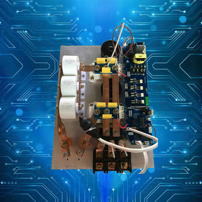
The electric heating control cabinet, designed for use with wellhead heaters, features a cabinet-type protective structure, constructed from thick steel plates that are bent and welded together. The shell is treated with electrostatic spray anti-corrosion technology. Inside, the cabinet is equipped with devices such as leakage circuit breakers, AC contactors, temperature control instruments, reactive power compensation components, and overheat protection relays. The control circuit is fitted with a main switch, allowing manual engagement and disconnection of the control circuit power supply.
Wellhead heaters come with electrical heating control cabinets suitable for their specific use environments, which are available in two specifications: general protection and explosion-proof types. The heating methods include two types: power frequency electric heating and constant temperature variable frequency electric heating, which are suitable for various heating processes and different usage locations.
Electromagnetic Heating Principle:
The heat carrier of the electromagnetic heater is wrapped around the core of an iron-magnetic steel pipe rod by a high-temperature heat cable, forming a magnetic closed loop by being structured into the sheath steel pipe. Due to the inherent properties of the iron-magnetic steel pipe, the current passing through the high-temperature cable circuit acts on the electromagnetic heat carrier rod, rapidly generating a strong hysteresis eddy current and magnetic resistance thermal effect. The stray magnetic field released by the heat carrier is shielded and absorbed by the outer steel pipe, producing skin effect heat within the ring, which is used for direct heating of oil. The reactive power consumed by the electromagnetic heater is compensated locally, resulting in a power factor of over 0.95. The reactive power consumed is directly converted into heat energy, used to heat the oil medium, thus achieving a thermal efficiency of over 98%. Compared to resistive heaters, under the same heating process conditions, its average energy-saving rate reaches 10-21%.
2. The electromagnetic heater features uniform surface heating without an open flame. It overcomes the high temperature defect of resistive heaters (exceeding 400℃ during operation) and boasts characteristics such as safety, explosion-proof, and a long service life (several times that of resistive heaters).
Principle: Utilizing the electromagnetic induction涡流 heating principle. An electromagnetic heater is a device that converts electrical energy into heat energy by employing the electromagnetic induction principle. The electromagnetic controller converts 220V, 50/60Hz AC into DC, and then transforms the DC into high-frequency high-voltage electricity at a frequency of 20-40kHz. The rapid changes in high-frequency high-voltage current passing through the coil generate a rapidly changing alternating magnetic field. When the magnetic lines within the field pass through ferromagnetic metal materials, numerous tiny eddy currents are induced within the metal, causing the material to heat up rapidly, thereby achieving the heating of the contents within the metal material cylinder.
Installation Points:
1. The main electromagnetic heater installation: Disconnect the gathering and pipeline, and connect the inlet and outlet oil gates to the inlet and outlet flanges of the wellhead heater, respectively, and then string them into the gathering and pipeline. In front of the inlet oil pipeline of the wellhead heater, connect a bypass gate for well washing, pipeline cleaning, and heater shutdown, allowing direct oil transfer through the bypass pipeline. 2. The wellhead heater is installed horizontally. The heater rod is securely fastened with a metal bracket, mounted approximately 0.5 meters above the ground. To prevent interference from well maintenance operations, the wellhead heater is installed at least 5 meters away from the wellhead production tree. 3. The control cabinet is securely fastened to the pre-fabricated heater bracket with screws and properly connected with grounding wires. The grounding or neutral wire cross-section is not less than 6mm copper core, with a ground resistance value not exceeding 4Ω. 4. The temperature control instrument sensor probe included with the cabinet is拧入the sensor mounting hole beneath the outlet oil flange, and its connecting control wires pass through the bottom of the cabinet and are securely fastened to the corresponding two terminal wires of the control wire terminal strip. 5. The installation of the wellhead heater and control cabinet must comply with explosion-proof requirements, and their wiring must meet the corresponding explosion-proof standards. When using a general type control cabinet in high oil and gas concentration areas, the control cabinet should be installed in an isolated electrical distribution room. The transmission wires and control cables used with the heater must meet the explosion-proof process requirements.
