
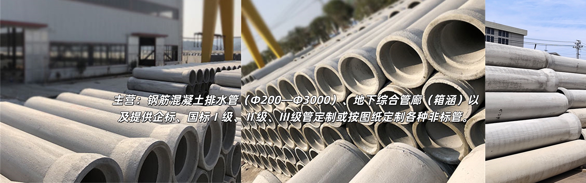
公司主营:Reinforced concrete drainage pipes (Φ200—Φ3000), underground utility tunnels (box culverts), and custom non-standard pipes as per drawings provided.
13645788727
企业资质
Key Points of the Full Process for Using Cement Drainage Pipes
2025-09-20
Cement drainage pipes, as critical components of infrastructure construction, their performance is not only dependent on the product's quality but also closely related to installation, inspection, and routine maintenance. The following outlines key points in the full process of using cement drainage pipes to ensure their stable drainage function.
Preparation Before Installation
Pipe inspection and selection
Visual InspectionInspect each pipe surface to ensure there are no obvious cracks, burrs, or exposed rebar, and that the pipe ends are smooth with no damage. Avoid using pipes with visible damage (minor blemishes should be evaluated for impact on sealing and structural integrity; replacements may be necessary if needed).
Size VerificationAccording to the design drawings, inspect the pipe materials for diameter, length, wall thickness, and other dimensions to ensure they match the engineering requirements. Simultaneously, verify the fitting accuracy of the socket and spigot connections to prevent installation difficulties due to dimensional discrepancies.
Intensive Quality InspectionRandomly selected sections of pipe materials are tested for concrete strength using a rebound meter to ensure compliance with engineering specifications (such as the common Grade II pipe strength, which must meet relevant industry standards). Non-compliant pipes are prohibited from being put into use.
2. Construction Site Preparation
Excavation of the foundation pitExcavate the foundation pit according to the design elevation and slope, ensuring sufficient space for operation (usually 30-50cm larger than the pipe outer diameter). The bottom of the pit must be level, avoiding any bumps or depressions.
Foundation TreatmentSelect the appropriate foundation treatment method based on soil conditions. In soft soil areas, a sand and stone cushion layer (typically 10-20cm thick) should be laid and compacted to ensure that the foundation's bearing capacity meets requirements and prevent pipeline settlement and deformation.
Materials and Equipment PreparationEnsure the availability of sealed gaskets (matching the pipe fitting sockets, ensuring no damage and good elasticity), sand and gravel backfill materials (with moderate particle size and low silt content), as well as cranes, excavators, and tools for gasket installation, etc.
Section II: Core Installation Process Standards
Pipe layout and connection
Pipe materials are in place.Using a crane, the piping materials are smoothly lifted into the foundation pit. Special lifting equipment is employed during the hoisting process to avoid direct binding of the piping, preventing damage. The materials are arranged in the installation sequence, with adjacent piping ends aligned, and leaving an appropriate joint gap (usually 5-10mm).
Seal Ring InstallationApply lubricant evenly to the O-ring (use specialized pipe lubricant or soap water; avoid oil-based lubricants that can damage the O-ring), then insert the O-ring into the groove of the pipe fitting, ensuring it is flat and undistorted, fitting snugly against the inner wall of the groove.
Pipe end connectionManually push the pipe with a hoist or by pushing from the top, ensuring the spigot is inserted smoothly into the socket. Maintain alignment of the pipe's axis throughout the insertion to prevent misalignment that could deform the gasket. The insertion depth must meet the design specifications (usually based on the socket marking) to ensure a proper seal.
2. Pipe Fixing and Adjustment
Slope CalibrationBy using a level instrument to measure the pipeline slope, we ensure it meets the drainage design requirements (such as municipal drainage pipes typically having a slope of not less than 0.3%). If there's a slope deviation, slight adjustments to the pipe material position can be made by placing a small amount of sand and gravel at the bottom of the pipes for leveling, but avoid over-elevating or lowering.
Temporary FixUpon completion of the connection, temporary sand and stone supports are used on both sides of the pipeline to prevent rolling or displacement, particularly on steep sections where additional stabilization is required. These supports are to be removed after backfilling is completed.
3. Compaction and backfill
Re-filling OpportunityAfter pipeline installation and completion of interface testing (no leakage), backfilling can commence. Backfilling should be done in layers, with each layer's thickness controlled at 20-30cm. Symmetrically backfill from both sides of the pipeline to avoid any displacement caused by uneven backfilling.
Strengthen requirementsTo compact backfill soil using a small roller or compactor, the area near the pipe wall (within 30cm of the wall) should be lightly compacted to prevent damage to the pipeline from the compaction equipment. After backfilling to 50cm above the pipe top, normal compaction can be applied to ensure the compactness of the backfill soil (typically not less than 90%), reducing subsequent settlement.
Post-installation inspection and acceptance
Sealability Testing
Closed Water TestFor wastewater pipelines or rainwater pipelines with seepage prevention requirements, a closed-water test must be conducted. Seal both ends of the pipeline, fill it with water to the specified level (usually 2 meters above the top of the pipe), and soak for 24 hours. After soaking, observe the water level drop. If the water level does not drop beyond the permitted range within 24 hours (the allowable seepage volume corresponds to the pipeline diameter, with a standard such as for a 500mm diameter pipeline, not more than 1.5L/(m・h)), and there is no leakage at the joints, it is deemed合格.
Chamber TestFor pressure-free rainwater pipes, a closed-gas test can be conducted by inflating the pipe to the specified pressure (usually 0.05MPa) and maintaining it for a certain period (usually 30 minutes). If the pressure drop does not exceed the specified value, the pipe is deemed qualified.
2. Comprehensive Acceptance
Aesthetics and DimensionsInspect the pipeline axis alignment, the flatness of the pipe ends' joints, and the evenness of the backfill surface; measure the actual gradient and elevation of the pipeline to ensure compliance with the design drawings.
Functional TestingThe water test was successfully conducted, observing that the pipeline drainage is smooth with no waterlogging or blockages, and the flow rate meets the design expectations, confirming the overall functionality of the pipeline.
IV. Daily Use and Maintenance
Regular inspections and maintenance
Routine inspectionRegularly (e.g., once a month) inspect the ground along pipeline routes for sinkholes and collapses, ensure manhole covers are intact, and check for clogged rain outlets; for pipelines buried deep underground, observe for sedimentation and leakage traces inside the pipeline through inspection wells.
Unclog and CleanEvery six months to one year (adjustable based on drainage volume and water quality), clear the pipes by using high-pressure water jets or mechanical dredging equipment (such as pipeline cleaning vehicles) to remove sediment and debris from inside the pipes, preventing blockages that could affect drainage. Special attention should be given to areas prone to sedimentation, such as bends and changes in pipe diameter.
2. Common FAQs Addressed
Pipe BlockageIf drainage is blocked, first determine the blockage location through the inspection well. For minor blockages, use a high-pressure water jet for cleaning. For severe blockages, employ淤泥清理 tools (such as bamboo strips, dredging claws) to clear the debris. If necessary, cut the pipeline to clear it and then repair the pipeline joints after it's unblocked.
Interface LeakIn case of minor leakage at the interface, clean the area around the interface and reapply sealing material (such as epoxy mortar); for severe leakage, remove the backfill soil at the interface, replace the sealing gasket, reassemble, and then conduct another leak-tightness test.
Pipe DamageFor minor damage (such as surface cracks), use patching mortar to fill and repair; for larger damage or when it affects the structural integrity, cut the damaged section of the pipe, replace with new materials, and ensure the overall integrity of the pipe.
Section 5: Usage Precautions in Special Situations
Low-temperature environment usage
In areas with low winter temperatures, it is essential to design pipe burial depths appropriately (below the local frost depth, typically not less than 1.2 meters) to prevent pipe freezing and cracking; if pipes are exposed outdoors (such as open trench drainage), insulation treatment is required (e.g., wrapping with insulation cotton, wrapping with thermal strips).
During winter drainage, to prevent long-term water accumulation and freezing inside the pipes, control the water discharge or flush the pipes regularly to avoid freezing blockages.
2. Corrosive Environment Use
If the pipeline is used for discharging corrosive wastewater (such as industrial wastewater), it is necessary to select corrosion-resistant cement drainage pipes (such as materials with added corrosion-resistant additives), and regularly inspect the internal wall corrosion of the pipeline. Replace it promptly if severe corrosion is detected.
The pipeline interfaces require enhanced sealing protection to prevent corrosive wastewater leakage from eroding the foundation or surrounding soil.
3. For high water level or pressurized environments
For drainage scenarios in areas with high groundwater levels or where pipes need to withstand certain pressures (such as pressure drainage pipes), it is crucial to ensure that the pipe's strength grade meets the requirements, while also reinforcing the compaction of backfill soil to prevent deformation of the pipe due to external water or soil pressure. Regularly inspect the pipe's pressure-bearing capacity to avoid damage caused by excessive pressure.
吕总 (Ms.)
13645788727
13645788727
168 Xianglong Road, Nanning Mountain Street, Liandu District, Lishui City, Zhejiang Province
www.114global.com © Zhongshang 114 Hebei Network Technology Co., Ltd.Address: Room 6009, Oriental New World Center, No.118 East Zhongshan Road, Qiaoxi District, Shijiazhuang City, Hebei ProvincePlatform Service Hotline: 4006299930