
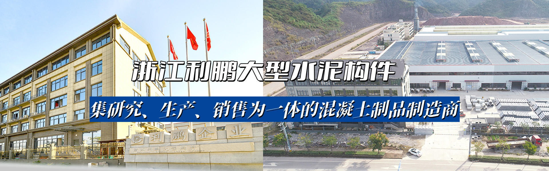
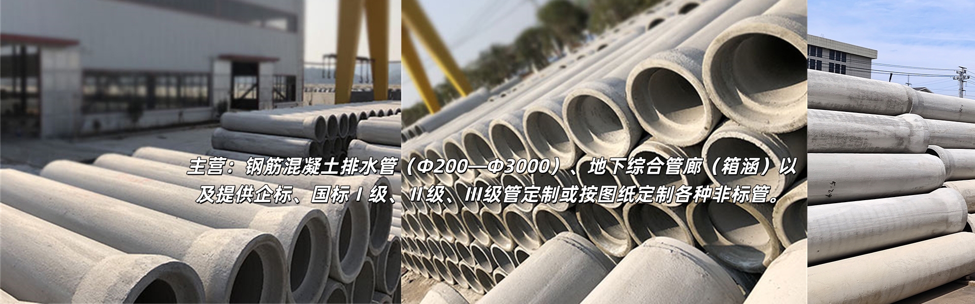
公司主营:Reinforced concrete drainage pipes (Φ200—Φ3000), underground utility tunnels (box culverts), and custom non-standard pipes as per drawings provided.
13645788727
企业资质
Precast Manhole Construction Full Process Standard
2025-09-20
Pre-cast manholes, as an essential part of the drainage pipeline system, play crucial roles in maintenance, sediment removal, and ventilation, with their construction quality directly impacting the stability of the entire drainage system. Below, we break down the full construction process of pre-cast manholes, in the order of construction, in conjunction with the cement pipeline installation project, to ensure smooth connection with the pipes and meet functional standards.
Pre-construction preparation phase
Technology and Solution Integration
In conjunction with the overall design drawings of the drainage system, clearly define the locations of precast inspection wells (such as at pipe bends, diameter changes, slope variations, and every 30-50 meters along straight sections), specifications (diameter, well height, chamber depth, etc.), and connection parameters with the pipeline (interface type, elevation difference, etc.). Develop a specialized construction plan and annotate the connection node requirements for the installation of cement pipes.
The construction team was organized for a technical briefing, emphasizing the accuracy of the junction between the inspection well and pipelines, the standards for foundation treatment, and the sealing requirements. Ensuring the construction personnel are familiar with the matching relationship between the inspection wells and pipelines as depicted in the drawings.
2. Pre-fabricated Components and Materials Preparation
Component SelectionPre-purchase prefabricated manhole components (including bases, cylinders, lids, rings, etc.) as per design specifications. Conduct individual inspections of each component prior to delivery for appearance (no cracks, missing corners, honeycomb surfaces, etc.), dimensions (diameter, wall thickness, interface sizes as per drawings), and verify the concrete strength test reports (typically requiring C30 or higher). Only upon meeting these standards may the components be delivered.
Supplementary MaterialsPreparing interface sealing materials (such as specialized sealing rings, waterproof mortar), bedding materials (graded sand and gravel, plain concrete), backfill materials (plain soil or gravel meeting compaction requirements), as well as reinforcement steel and concrete for well cover reinforcement, to ensure compatibility with precast components.
3. Equipment and Facility Preparation
Equipment CommissioningEquipped with cranes (with specialized lifting equipment to prevent damage to components), excavators (for foundation excavation), leveling instruments (for elevation calibration), compaction machines (for subgrade and backfill compaction), and troweling tools (for interface treatment), the equipment was pre-inspected to ensure proper operation.
Site PreparationIn the well-casing construction area, obstacles were cleared, the ground was leveled, and component storage areas were designated (requiring elevation, rain protection, and moisture prevention to avoid component damage). Maintained a reasonable distance from the cement pipeline storage area, while also ensuring temporary drainage to prevent ground waterlogging that could affect construction.
Excavation of the foundation pit and ground treatment phase
Excavation survey and stakeout
According to the design drawings, locate the center of the precast inspection well using a total station, and draw the excavation edge line from the center (the excavation diameter needs to be 40-60cm larger than the outer diameter of the inspection well to reserve operating space). Set control stakes to mark the excavation depth (calculate based on the well room design depth, bedding thickness, and pipe burial depth).
Excavation work for the foundation pit is underway.
Using excavators for layered excavation, the depth is continuously monitored by a leveling instrument during the process to prevent over-excavation. If the excavation depth exceeds 1.5 meters, slopes must be graded according to soil type (e.g., clay with a slope ratio of 1:0.5) or support structures (such as steel sheet piles) must be set up to prevent the collapse of the foundation pit. When excavation reaches 10-15cm above the designed elevation, switch to manual cleaning of the base to remove debris, ensuring a flat base.
If there is groundwater at the bottom of the foundation pit, a sedimentation well and a pump must be installed for drainage. Construction should only proceed once the water level has dropped 50cm below the base to prevent the soil from being softened by water saturation.
3. Foundation Reinforcement Treatment
If the base is in its original state of soil and meets the load-bearing requirements (determined by the flat-plate load test, which must satisfy the weight of the precast inspection well and the upper loads, typically not less than 120kPa), directly level the surface and pour a 10-15cm thick C15 plain concrete base course, finishing and compacting the surface. For soft soil, silt, and other weak foundations, it is necessary to first replace the base with graded sand and gravel (rammed in layers, each layer 20cm thick, with compaction not less than 93%), then pour the plain concrete base course to ensure the stability of the foundation and prevent the inspection well from sinking.
III. Pre-fabricated Component Installation Phase
Wellhead Installation and Calibration
Once the subgrade concrete reaches over 70% of its design strength, the well seat is gently lowered into the foundation pit using a crane, aligning the center of the well seat with that of the pit. The level is then used to calibrate the elevation of the well seat, ensuring the top surface of the well seat meets the design requirements (matching the elevation of the surrounding road or ground), with the deviation kept within ±5mm.
After the wellhead is positioned, backfill around it with sand and gravel to reach half the height of the wellhead, compact in layers (with compaction rate not less than 90%), temporarily secure the wellhead to prevent displacement.
2. Cement pipeline connection construction
Interface HandlingClean the reserved interfaces of the well seat (the socket or plug for connecting with the cement pipe) and the ends of the cement pipe, removing oil and debris; insert the special sealing gasket into the凹槽 of the well seat interface, apply lubricant, and slowly push the cement pipe until the pipe end is smoothly inserted into the well seat interface, ensuring the insertion depth matches the interface marking and maintaining a tight seal.
Axial AlignmentDuring the connection, a dedicated person monitors the alignment of the pipeline and the well seat's axis to ensure the pipeline's centerline aligns with the well seat's interface centerline, with an allowable deviation of no more than 10mm. If there is a height difference between the pipeline and the well seat, fine-tuning is required by adjusting the pipeline's bottom bedding (adding a small amount of sand and gravel, not exceeding 5cm in thickness). It is strictly prohibited to force the connection, which may damage the interface.
3. Casing and Collar Installation
Casing InstallationBased on the design well depth, select the appropriate length of well casing components. Clean the top surface of the well pad and the bottom interface of the well casing. After applying waterproof mortar, hoist the well casing smoothly onto the well pad, aligning the interface between the casing and the pad, and gently secure it in place. If the well casing is too short and requires splicing, apply waterproof mortar at the joints, reinforce the splice with steel hoops (spacing 30 cm), ensuring the joints are tight and secure.
Borehole Casing InstallationUpon completion of the wellbore installation, a wellhead collar is mounted at the top of the wellbore, aligning its elevation with that of the surrounding road or ground level (the road collar should be 5-10mm below the road surface for ease of fitting the manhole cover flush with the road). Fill the gap between the collar and wellbore with cement mortar, compacting and smoothing it.
Stage 4: Interface Sealing and Waterproofing Process
Interface sealing construction
At the wellhead and pipeline junction: Wrap glass fiber cloth around the outer side of the junction, apply two layers of polyurethane waterproofing paint (thickness not less than 1.5mm), or seal with waterproof mortar in layers, covering both sides of the junction for 15cm width, ensuring no leakage.
At the wellbore splicing interface: The interface外侧 is pressed into an arc shape (radius not less than 5cm) using polymer cement mortar, the surface is polished, and a cementitious penetrating crystalline waterproof coating is applied after the mortar has set to enhance the waterproof effect.
2. Well Sealing Treatment
Once all interfaces are sealed, clean the interior walls (well base, well shaft) of the inspection well. After drying, apply cement-based waterproof coating (thickness not less than 1.2mm), focusing on the interfaces and corners of the well walls to ensure even coverage and no missed spots, forming a complete waterproof layer.
V. Backfilling and Compaction Phase
Preparation before backfilling
Inspect the precast manhole installation location, elevation, and interface sealing quality to ensure compliance with design requirements; clean up debris and standing water in the foundation pit. If a water-tightness test is required (to be conducted simultaneously with the pipeline), backfilling should only be done after the test passes.
2. Layered backfilling construction
Backfill soil should be composed of clean soil or graded sand and gravel (free of large stone or frozen soil blocks), and it should be symmetrically layered around the inspection well, with each layer being 20-30cm thick to prevent the well shaft from shifting or joints from deforming due to uneven backfilling. When the backfill reaches two-thirds of the well shaft height, pause the backfilling and perform a second compaction on the gaps between the well wall and the backfill soil before continuing to backfill to the ground level.
Layered compaction operation
Within a 30cm radius of the wellbore wall, use a small compactor for light pressing (with compaction rate not less than 90%) to avoid direct impact of the compaction equipment on the wellbore; outside a 30cm radius of the wellbore wall, use a compactor or a small roller to compact (with compaction rate not less than 93%); if the inspection well is located beneath a road, after backfilling to 50cm above the pipe top, the roadbed compaction standards must be followed (with compaction rate not less than 95%) to ensure stable road surface load-bearing.
Section 6: Manhole Installation and Surrounding Treatment Phase
Manhole Cover Installation
Once the concrete mortar around the well ring reaches more than 70% of the designed strength, install the manhole cover: Place the cover into the ring, adjust its level, ensuring a tight fit between the cover and the ring for smooth operation. For heavy-duty manhole covers (used on roadways), install shock-absorbing strips between the cover and the ring to reduce noise during vehicle passage.
2. Surrounding Roadway (Surface) Treatment
If the manhole is located on the road surface, after the cover is installed, cast C30 concrete around the manhole cover (30-50cm larger than the collar, with the same thickness as the road surface). The surface work should be synchronized with the road material (asphalt, cement concrete) to ensure the cover is level with the road surface without any height difference. If it's in a non-road area (such as a green belt, pedestrian walkway), lay permeable bricks or plant soil around the manhole cover to harmonize with the surrounding environment.
Section 7: Inspection and Acceptance Phase
Appearance and Dimension Inspection
Inspect prefabricated manhole appearance: wall without damage or cracks, joints sealed tightly, and facing smooth; measure the deviation of the center position of the manhole (not exceeding 15mm), elevation deviation (±10mm), and verticality of the manhole (not exceeding 5mm per meter) to ensure compliance with design specifications.
2. Sealing Integrity Test (Water Tightness Test)
Concurrently with the closed-water test for cement pipes: Seal both ends of the manhole and the connected pipes, fill the system with water to 20cm above the top of the well, soak for 24 hours, then observe the water level drop within 24 hours. Check for leakage at the manhole interfaces, well walls, and junctions with the pipes; the allowable leakage rate must meet the standard requirements (e.g., for a 500mm diameter pipeline system, the allowable leakage rate should not exceed 1.5L/(m・h)). No leakage indicates a pass.
3. Functional Acceptance
Inspecting Manhole Covers: The junction of the manhole base and well shaft is secure, and the covers open smoothly; a sedimentation test was conducted on the connecting pipelines through the manholes, confirming there is no waterlogging inside and the drainage of the pipelines is unobstructed, meeting the requirements for maintenance and sediment removal.
4. Documentation Acceptance
Organize construction documents: including quality certificates for precast manhole components, inspection reports, construction records (excavation, foundation treatment, installation, waterproofing, backfilling, etc.), water-tightness test reports, acceptance sheets, etc., to ensure completeness and standardization of the documents, consistency with on-site construction, and ultimately pass the supervision and acceptance by the construction unit.
吕总 (Ms.)
13645788727
13645788727
168 Xianglong Road, Nanning Mountain Street, Liandu District, Lishui City, Zhejiang Province
www.114global.com © Zhongshang 114 Hebei Network Technology Co., Ltd.Address: Room 6009, Oriental New World Center, No.118 East Zhongshan Road, Qiaoxi District, Shijiazhuang City, Hebei ProvincePlatform Service Hotline: 4006299930