Engaging in the design of combustion equipment, explosion...

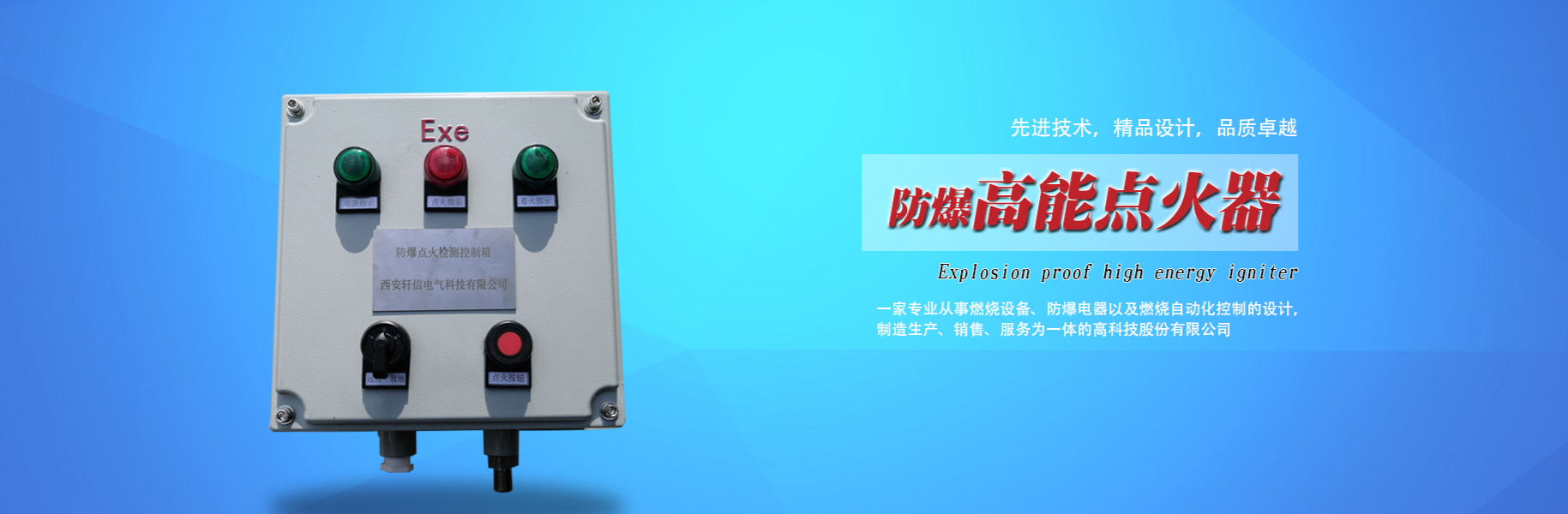
The explosion-proof ignition control box XGD-20 is primarily used for the automatic ignition of industrial burners. This igniter is compact in size, powerful in energy, with a high-temperature-resistant ignition end, and is resistant to carbon accumulation and coking, featuring self-cleaning capabilities and reliable ignition.HighIts performance exceeds imported ignition transformers, with easy installation of the ignition gun and no need to adjust the ignition electrode discharge distance.
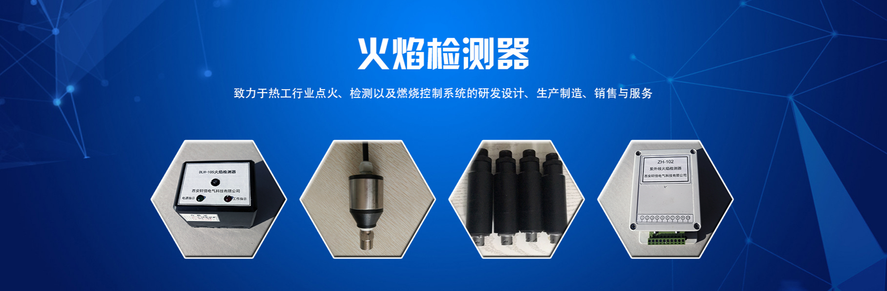
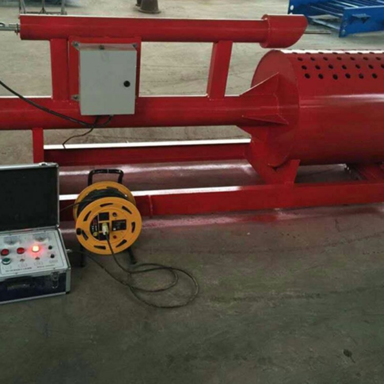
The explosion-proof ignition control box is mainly composed of an explosion-proof control box (including a 20J igniter) and high-voltage connection wires.Ignition RodThe ignition equipment consists of several components. It can be operated locally through panel buttons or remotely via PLC control. The product features a high-performance ignition circuit, offering stable performance and reliable operation.
Explosion-proof Control Box Panel Instructions: The explosion-proof control box panel features a power indicator light, a local-to-remote switch, and a manual ignition button.
Technical Specifications for Explosion-Proof Igniters
Power Voltage: 220V ± 10% 50/60 Hz
2. Applicable Fuels: Natural Gas, Diesel, etc.
Spark Energy: 20J
Spark Frequency: 8-14 Hz
3. Ignition Rod with Temperature Resistance up to 1300℃
Section 3: Explosion-proof control box objects
Material: Aluminum alloy; Explosion-proof grade: ExdeIIBT4; Protection grade: IP65.
2. Volume: 300×300×140mm
3. Installation Dimensions - Rectangular diagonal installation, mounting holes Φ8mm
Two,Explosion-Proof High-Energy IgniterInstallation and Wiring
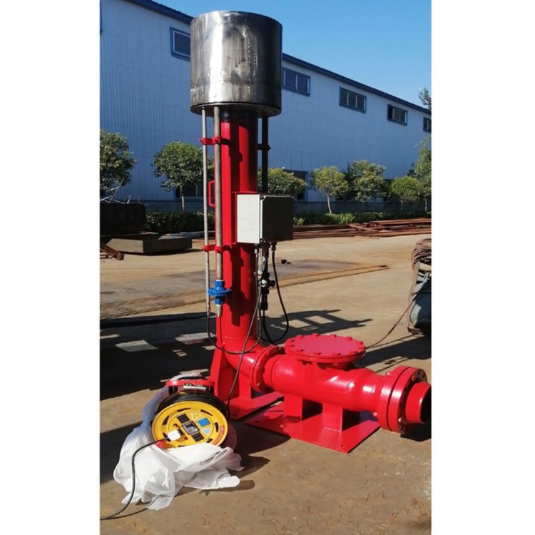
1. (1) The application is for a burner, featuring a φ16.5 hole machined with an M18×1.5 mounting thread. Simply screw the ignition rod in, and the ignition rod's firing end is installed 30 to 50mm in front of the nozzle.
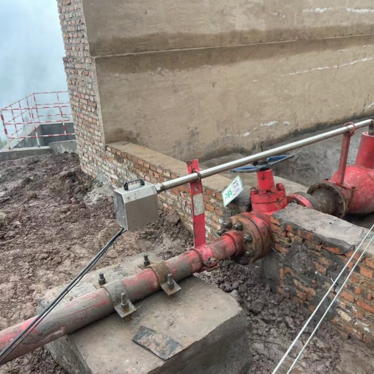
(2) For the application of torch release, the ignition rod must be secured with a dedicated ignition rod clip, with the firing end of the ignition rod positioned 100-200mm from the release opening. This ignition rod features a new structure design, eliminating the need for adjustment of the discharge distance.
2. The seriesIgnition DeviceThe system is composed of three parts: the explosion-proof housing, a dedicated ignition cable, and an ignition rod. Upon installation, simply connect the ignition device housing and the ignition rod with the dedicated ignition cable, and the power supply is 220v.ac.
Three: Explosion-proofHigh-Energy IgniterNo Chinese content provided.
1. Once the fuel is ignited, the igniter should be turned off immediately. To prevent internal components from burning out due to prolonged continuous ignition, a protective module has been added to the igniter. Continuous ignition for 10 seconds will automatically cease the ignition output. Pressing the local ignition button again or reconnecting the remote drive will resume ignition.
Ensure the furnace is swept clean of any residual combustible gases prior to ignition to prevent explosive accidents and personal injuries during the initial点火 process.
3. The igniter is used during fuel ignition, and the fuel should be well atomized. Poor atomization quality can affect the success rate of ignition. After ignition is complete, use the propeller or manually withdraw the ignition rod from the flame combustion zone to **extend the service life of the ignition rod.**
4. Avoid dropping or bumping the ignition rod during installation and use to prevent the porcelain insulator from cracking, which could lead to high-voltage leakage and failure to ignite, severely affecting the equipment's normal operation.
When igniting, the ignition device should be turned on first, followed by fuel injection and ignition.


www.114global.com © Zhongshang 114 Hebei Network Technology Co., Ltd.Address: Room 6009, Oriental New World Center, No.118 East Zhongshan Road, Qiaoxi District, Shijiazhuang City, Hebei ProvincePlatform Service Hotline: 4006299930