

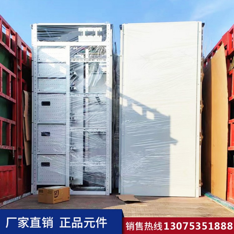










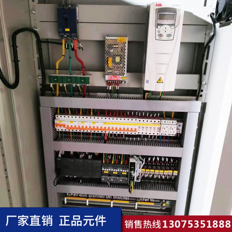
Low-voltage distribution board
Products for converting and configuring electrical power
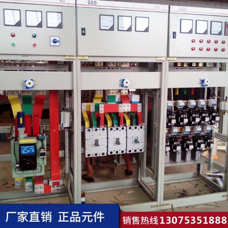
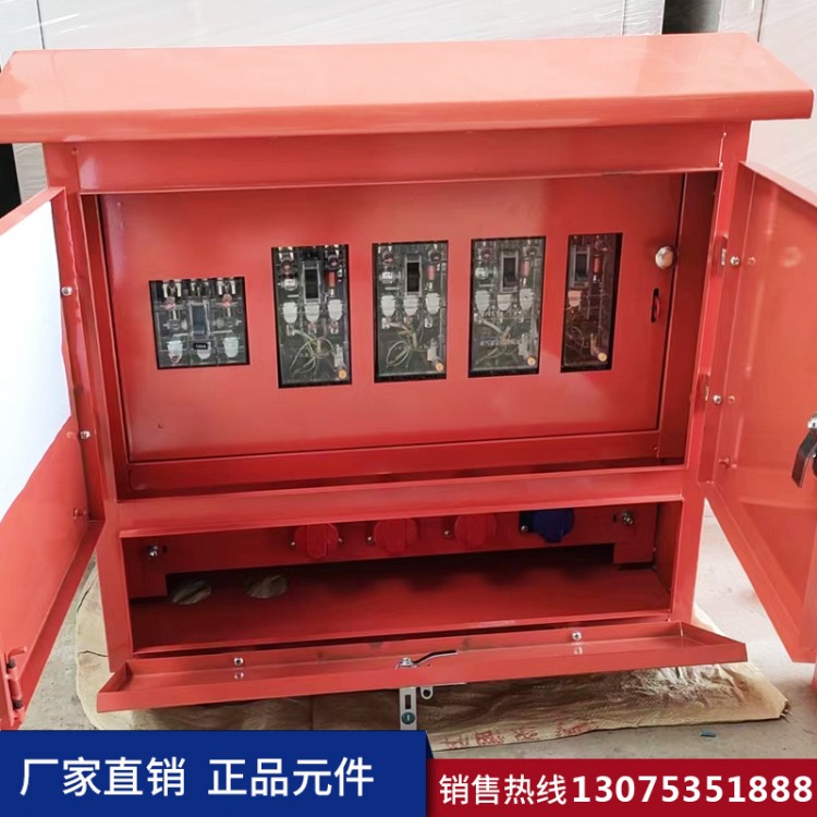
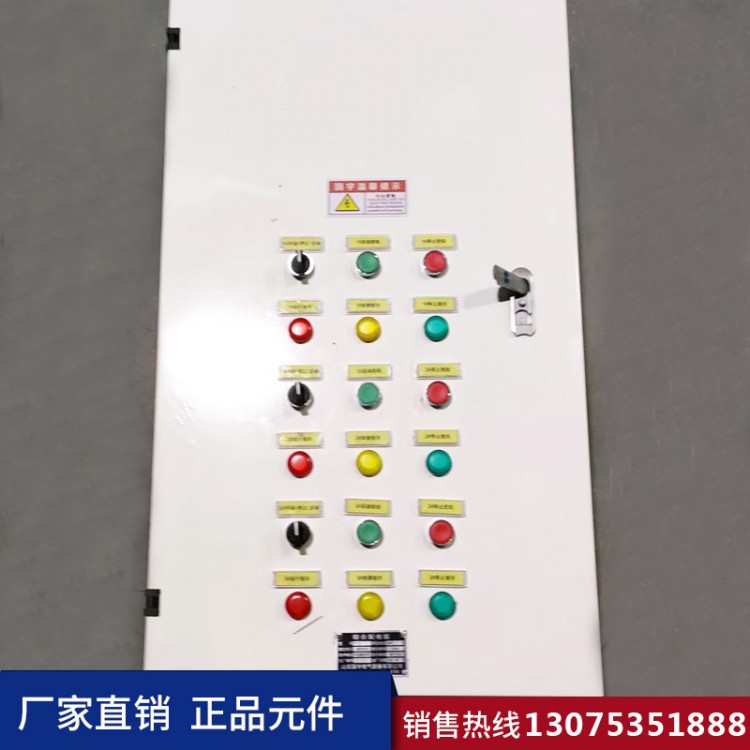
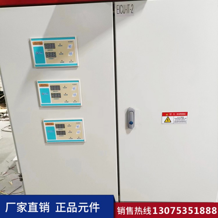
The low-voltage distribution box is equipped with a power distribution system rated for an alternating current of 50Hz and a voltage of 380v, used for power, lighting, and power distribution electrical energy conversion and control. This product features strong breaking capacity, good dynamic and thermal stability, flexible electrical design, convenient assembly, strong series characteristics, and innovative structure.
Current Development Status
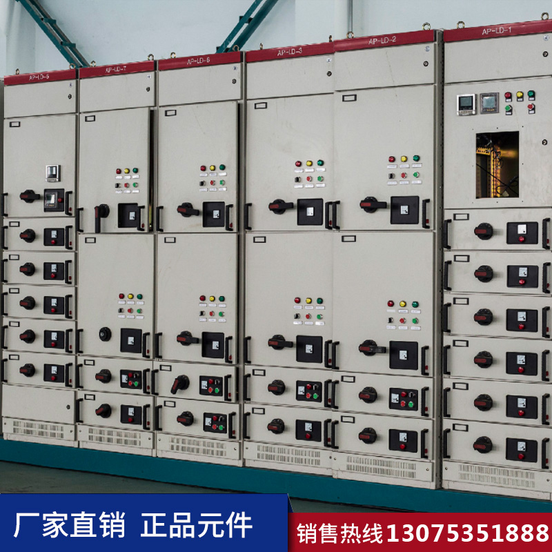
1: Low-voltage complete switchgear and control equipment, commonly known as low-voltage switchboards, are also referred to as low-voltage distribution boards. They refer to complete electrical installations with alternating or direct current voltages below 1000V.
2: The low-voltage distribution cabinet market in our country has maintained a rapid growth momentum with the construction of smart grids, infrastructure, manufacturing investments, and the development of the new energy industry.
3: Data shows that in 2010, the total sales of low-voltage distribution cabinets in China reached 10.633 billion yuan, with a year-on-year increase of 11.2%; in 2011, the total sales of the low-voltage distribution cabinet market in our country reached 11.96 billion yuan, a year-on-year increase of 12.5%.
4: With the robust demand for low-voltage distribution cabinets in our country, internal industry competition will inevitably intensify. Suppliers offering the next-generation low-voltage integrated equipment and system solutions will gain a competitive edge in the future market. Only products with the aforementioned features can secure a certain advantage in future competition, thereby occupying the commanding heights of the fourth-generation low-voltage electrical products.
Product Range
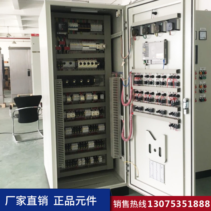
GCS container
Primary Structure
The main structure is made of 8MF type open steel, with installation holes of 9.2mm diameter on the steel side, respectively measuring 20mm and 100mm in modulus.
2: The functional compartments of the device are isolated from each other, divided into unit rooms, busbar rooms, and cable rooms. The functions of each room are independent of one another.
3: Horizontal main busbars are arranged in a flat placement behind the cabinet to enhance their resistance to electromagnetic force.
The design of the cable compartment facilitates easy in-and-out access for cables both vertically and horizontally.
Functional Unit
Drawer height module is 160mm, unit circuit rated current 400A and below
GCK Container: (MCC)

Primary structure
GCK(L) Type Low-Voltage Distribution Box
GCK (L) Type Low-Voltage Distribution Box
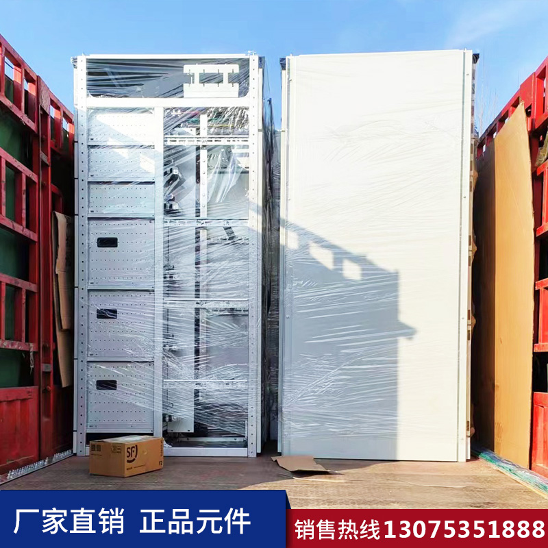
The basic structure of the cabinet is a modular assembly. Bolted connections secure the 20mm modular installation holes, with each functional compartment isolated. The fundamental feature of the GCK cabinet is that the busbar is located at the top of the cabinet, with compartments divided into functional units (in front of the cabinet), busbar room (at the top of the cabinet), and cable room (at the back of the cabinet). It can also be mounted against a wall, where the cabinet's right side is widened by 200mm to accommodate the cable room, resembling the top busbar style of the MNS cabinet.
Function Unit
Drawer height modular 200mm
MNS Container: (MCC)

Primary structure
MNS Type Distribution Box
MNS Type Distribution Cabinet
The cabinet's basic structure is assembled from C-shaped profiles. The C-shaped profiles are formed by bending steel plates with mounting holes at a module of E=25mm.
2: The pull-out MCC cabinet is divided into three compartments, which are the functional unit compartment (on the left side in front of the cabinet), busbar compartment (rear of the cabinet), and cable compartment (on the right side in front of the cabinet). Due to the horizontal busbar compartment being at the back, it can also be designed as a double-sided cabinet.
3: Designed to reduce the width of switchgear arrangement, the rear outlet switchgear has the main busbar horizontally installed at the top of the switchgear. The rear half of the cabinet serves as the cable room, similar to the busbar style in GCK switchgear.
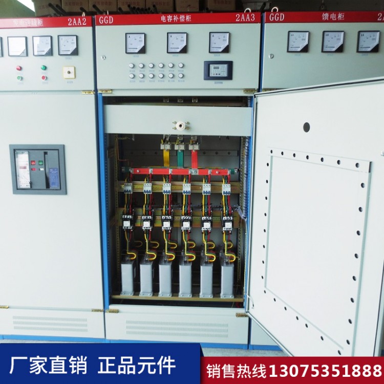
GGD Container: (ESS)

Electrical Performance:
1) Basic Electrical Parameters
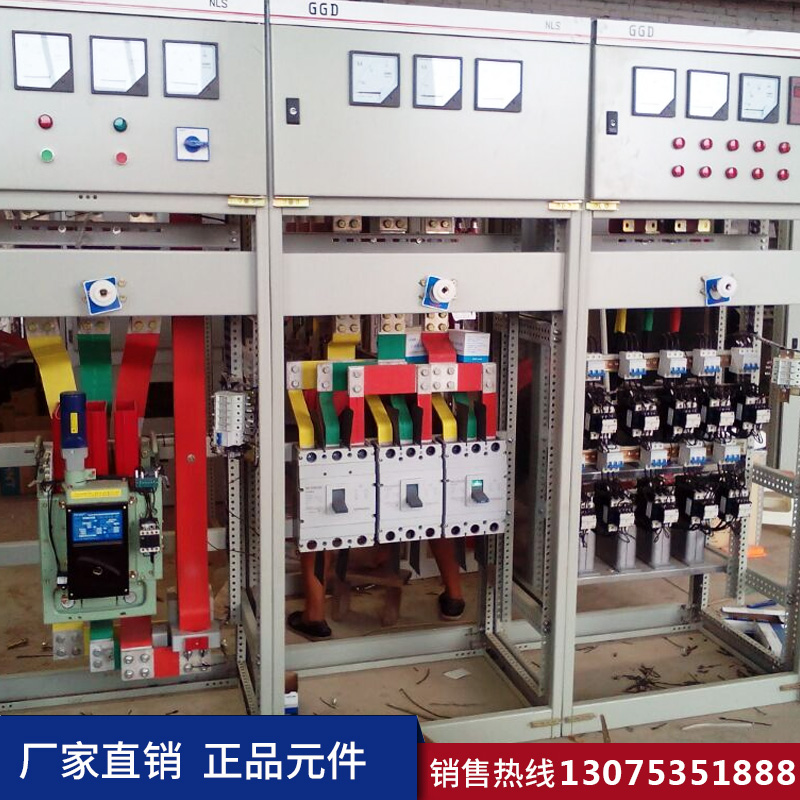
GGD Type Low-Voltage Distribution Box
GGD Type Low-Voltage Distribution Box
A) Rated Insulation Voltage: AC 660V (1000V) B) Rated Working Voltage: Main Circuit: AC 380V (660V); Auxiliary Circuit: AC 380V (220V), DC 220V (110V)
C) Rated Frequency: 50Hz
D) Rated Current: ≤ 4000A
E) Rated Peak Current Tolerance (0.1s): 105KA
F) Rated Short-Time Current Tolerance (1s) 50KA
The GCK series AC low-voltage distribution cabinets are recognized as a new energy-saving product by the state. They feature an advanced control center structure, attractive appearance, high electrical performance, high protection grade, safety, reliability, and ease of maintenance. They are the ideal power distribution units for low-voltage power supply systems in industries such as metallurgy, petrochemicals, chemical engineering, electrical machinery, and light industry.
Primary Technical Performance
b) Rated Working Voltage: 380V, 660V
c) Frequency: 50Hz
d) Rated Current: Horizontal Busbar System 1600-3150A, Vertical Busbar System 400-800A
e) Rated Short-Time Current Endurance: Horizontal Bus 80KA RMS/1 sec; Vertical Bus 50KA RMS/1 sec
f) Rated Peak Current: Horizontal Bus 175KA, Vertical Bus 110KA
g) Functional Unit Break Capacity: 50KA
h) External Equipment Protection Class: IP40
PGL cabinet:
The PGL type AC low-voltage distribution cabinet is suitable for power users such as power plants, sub-stations, and industrial and mining enterprises in distribution systems for AC 50Hz, rated working voltage 380V, and rated current up to 2500A. It is used for power conversion, distribution, and control of power, lighting, and distribution equipment. This product has high breaking capacity, with a rated short-time withstand current of up to 50kA.
This product complies with standards IEC 439 for Low-voltage switchgear and controlgear, GB 7251 for Low-voltage switchgear and controlgear, etc.
PGL Distribution Cabinets are designed for indoor installation, featuring an open-type, double-sided maintenance low-voltage power distribution unit. The basic structure of the cabinet is composed of steel plates and angle steel焊接. The front of the cabinet is equipped with a door, and above the cabinet is an instrument panel, which is a removable small door for installing indicator meters. The cabinets, assembled in parallel, are separated by partition panels to minimize the possibility of accidents caused by a single cabinet failure. Above the rear frame of the cabinet, the main busbars are installed on sub-insulating frames, and busbar protective covers are provided to prevent metallic objects from falling and causing a catastrophic short circuit of the main busbars. The neutral busbar is mounted on insulators below the cabinet, and the main grounding point of the grounding system is welded below the frame. The instrument door also has a grounding point connected to the housing.
PGL type AC low-voltage distribution panels are divided into: low-voltage metering cabinets, low-voltage incoming line cabinets, capacitor compensation cabinets, municipal power generation conversion cabinets, bus connection cabinets, and low-voltage outgoing line cabinets.
Key Technical Parameters:
Rated Voltage: AC 380V
Rated Breaking Capacity:
PGL1:15KV
PGL2: 30KV (all are RMS values)
Rated voltage of auxiliary circuit:
AC220V、380V
DC110V、220V
Rated Current:
2000A,2500A

Maintenance Instructions
The maintenance of low-voltage distribution cabinets primarily ensures their normal and safe operation. An annual comprehensive inspection and maintenance of low-voltage distribution cabinets is required. Repairs should be completed with minimal downtime, typically scheduling the owner's power outage time in advance.
Maintenance Content and Steps for Low-Voltage Distribution Cabinets:
1: Start the inspection from the low-voltage side of the transformer. After the distribution cabinet is de-energized, clean the dust inside, check for good connections of busbars and down leads, look for overheating or discoloration at the joints, ensure the cable heads and terminal posts are secure and reliable, inspect for rust on the grounding wires, and verify that the terminal posts are tightly fastened. All secondary circuit wiring connections should be reliable and insulated to meet requirements.
2: When checking the drawer-type switch, the drawer cabinet should operate smoothly upon insertion or extraction, with a reliable mechanical lock. Verify that the operating mechanism of the automatic air switch on the drawer cabinet is in place and that the wiring screws are tightened. Clean the contactor contacts and their surroundings, ensuring proper contact. If the contacts are not making good contact, lightly file the contact surface as necessary. If the contacts are severely burned (the contact point is worn down to 1/3 of the original thickness), they should be replaced. The power indicator gauge and indicator lights are in good condition.
3: When inspecting the capacitor cabinet, first disconnect the main switch of the capacitor cabinet. Use a wire with a cross-sectional area of 10mm² or more to discharge each capacitor to ground individually. After visual inspection, ensure the cabinet shell is in good condition with no oil leakage. If the capacitor shell swells, handle it promptly by replacing the discharge device, control circuit wiring screws, and grounding equipment. After closing the circuit, adjust the indicator and automatic compensation sections.
4: Maintenance of circuit breakers in switchboards and relay cabinets: After disconnecting all loads, manually pull out the circuit breaker using the handle. Re-tighten the wiring screws and check if the spring force of the blade is as specified. Inspect for any cracks or damage in the arc extinguishing grid. Manually adjust the mechanical interlock to ensure proper opening and closing. Check the contact points for good contact, and if necessary, file the surface of the contacts. Inspect the internal springs, washers, and screws for looseness, deformation, or detachment.
Transformer substation maintenance:
Prior to operation, follow these steps: disconnect the loads on the low-pressure side one by one, trip the circuit breakers on the high-pressure side, close the grounding switch, and lock the high-voltage switchgear. Then, attach a "Do Not Close, Person Working" sign to the switchgear handle, short-circuit the busbars with 10mm2 or thicker wiring and hang the grounding wire, and tighten the busbar screws.
2: Maintenance Operation Steps: Clean the busbar contact area thoroughly, apply electrical composite grease, secure with new spring washers and screws, inspect for any abnormalities in the insulators and spacing connections between busbars, and verify the reliability of the connections at the secondary winding terminals of the current, voltage, and transformer.
3: Pre-power supply inspection and testing: Remove all grounding wires and jumper cables, check for any tools left at the work site, confirm there are no issues, then close the isolator switch, disconnect the high-voltage side grounding switch, close the high-voltage side circuit breaker of the operating transformer, remove the signage, supply power to the transformer, then close the circuit breaker of the low-voltage receiving cabinet, supply power to the busbars, and finally close the relevant interconnection cabinets and automatic air switches of each branch.
Cautionary Notes:
1: A designated person must be on duty to supervise during the maintenance process.
2: Electrical testing must be conducted before operation.
3: Maintenance personnel should be familiar with and operate the electrical mechanical interlock system of the entire distribution cabinet.
4: Be sure to detail which lines are dual-powered during maintenance.
When inspecting busbars, ensure that the residual charge in the lines is fully discharged.
Inspection Process
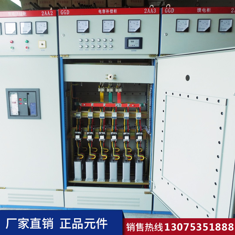
The inspection process for low-voltage distribution cabinets is divided into two parts:
Firstly, the structural part inspection, which is the inspection of the box size, a random check of standard cabinets is sufficient.
Secondly, electrical inspection is required. Firstly, according to the technical drawings, check the component models, verify the torque of the connection points, and make markings (this task is quite labor-intensive and requires a thorough check). At the same time, pay attention to the creepage distance and the inter-phase distance to ensure they meet the standards, and check if the wiring complies with the company's process requirements. Then, verify if the main and control circuits are correct, primarily using a multimeter to measure the wires. Next, perform an electrical function test to see if it meets the drawing requirements. Whether it passes or fails, a test report must be issued. Products that pass are labeled and shipped, while those that fail are returned for correction.
Cabling
One, Location: To ensure the normal and safe operation of low-voltage distribution cabinets, the location of the low-voltage distribution room should be close to the load center. The placement area should be free of dust and corrosive substances; otherwise, they should be cleaned promptly. For safety, the environment should be relatively dry, and the placement should minimize vibration.
II. Layout of Power Distribution Equipment: The arrangement of power distribution equipment in low-voltage distribution rooms must prioritize safety, reliability, suitability, and economy, while also ensuring ease of installation, operation, handling, maintenance, testing, and monitoring. Sufficient spacing and exit pathways must be provided for electrical equipment rooms housing both low and high-voltage equipment, as well as for rows of distribution cabinets. Necessary safety measures should be taken when arranging power distribution equipment, including the use of protective covers or placement beyond the reach of a person's extended arm for any exposed live conductors with hazardous voltages. In cases where it is difficult to use protective covers and outer shields, barriers can be used for protection.
III. The layout of the distribution lines should meet the following conditions: conform to the environmental characteristics of the placement location, comply with the characteristics of the building, consider the moderate distance between people and the lines, account for mechanical and electrical stresses that may arise due to short circuits, and consider other stresses that the wiring may be subjected to during installation and use, as well as the weight of the conductors.
Four, factors affecting the arrangement of distribution lines: preventing external heat from affecting use, preventing water entry from affecting use, preventing external mechanical damage from affecting use, preventing dust accumulation on wiring from affecting use, and preventing strong radiation from affecting use.