


I. Principle
The working principle of the ultrasonic level gauge involves a transducer (probe) emitting ultrasonic pulses that are reflected off the surface of the medium being measured and then returned. A portion of the reflected waves is received by the same transducer and converted into electrical signals. Ultrasonic pulses propagate at the speed of sound, and the time interval from emission to reception of the ultrasonic pulse is proportional to the distance between the transducer and the surface of the medium being measured. The relationship between this distance value S, the speed of sound C, and the transmission time T can be expressed by the formula: S = C x T / 2.
Due to the finite width of the ultrasonic pulse emitted, the reflected waves from the shorter segments closer to the transducer overlap with the emitted waves, making them indistinguishable and unable to measure their distance values. This area is referred to as the measurement blind zone. The size of the blind zone is related to the model of the ultrasonic level gauge.

Section II: Features
Due to the use of advanced microprocessors and unique echo processing technology, ultrasonic level gauges can be applied to various complex operating conditions. "Transducer built-in"Temperature sensorThe device can achieve temperature compensation for measured values. The ultrasonic transducer's emission power can be adjusted in real-time based on echo analysis algorithms, thereby ensuring accurate measurement.
1. Power Supply Voltage
4...20mA/HART (two-wire system) - Power supply and current signal share a two-core cable. Specific power supply voltage range is detailed in the technical data. For intrinsically safe models, a safety barrier must be installed between the power supply and the instrument.
4...20mA/HART (4-wire system) - Power supply and current signal each use a separate two-core cable. Specific power supply voltage range please refer to technical data.
Standard-type instrument current output can be grounded. Explosion-proof instrument current output must be floating. The instrument and grounding terminals should ensure a good ground connection, usually connected to the tank's grounding point, and if the tank is plastic, it should be connected to the nearby ground.
Cable Connection Installation
2. General Introduction
Power cables can utilize standard two-core cables, with an outer diameter of 5...9mm to ensure the seal of the cable entry. If electromagnetic interference is present, it is recommended to use shielded cables.
4...20mA / HART (two-wire system) - Power cables can be standard two-core cables.
4...20mA/HART (4-wire system) power supply cables should be shielded cables.
Cable shielding and wiring
Both ends of the shielded cable should be grounded. Inside the sensor, the shield must be directly connected to the internal grounding terminal. The external grounding terminal on the housing must be connected to the earth.
If there is a grounded current, the shielded cable's shield terminal on the side away from the instrument must be grounded through a ceramic capacitor (e.g., 1μF 1500V) to suppress low-frequency grounded currents while still preventing high-frequency interference signals.
This product requires a safety barrier for power supply. The AO5041-1 safety barrier is an associated device of this product, featuring intrinsic safety as the explosion-proof type. Explosion-proof marking: [Exia] II B, power supply voltage 24V DC ±5%, short-circuit current 100mA, operating current 4…20mA.
All cables must be shielded, with a length of 500 meters. Distributed capacitance ≤0.1μF/Km, distributed inductance ≤1mH/Km. The ultrasonic level gauge must be grounded during installation. No other related equipment that has not passed explosion-proof inspection may be used.
Internet of Things (IoT) Products:
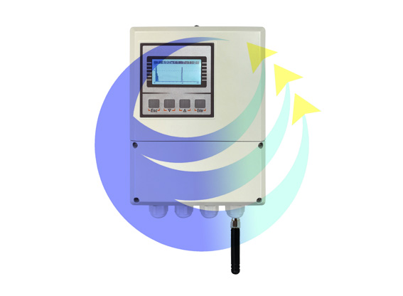
12VDC power supply, RS485 output, low power consumption, economical, suitable for extensive deployment, used for water level measurement in rivers, canals, and channels!
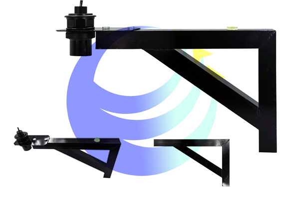
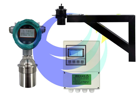
Mounting Bracket: