


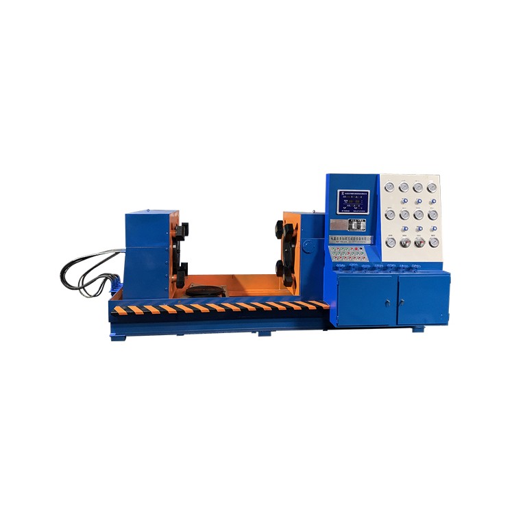


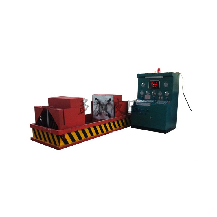
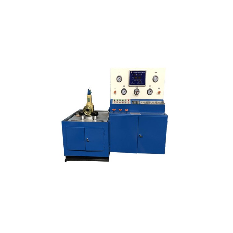

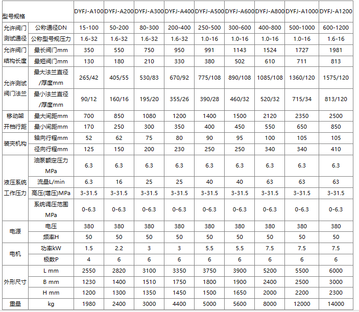
DYFJ-A800型阀门试验台是多加液压公司积累多年生产经验基础上,按照国家标准规范要求,自行研制的第四代阀门试压检测设备。
DYFJ-A800型阀门试验台集机电、液压系统、试压、液体介质贮存循环使用于一体,具有功能完善、性能稳定、自动化程度高等特点。广泛应用于公称通径400-800mm直通法兰式各类高、中、低压阀门的密封面泄漏测试、壳体强度(沙眼)等各项性能测试。测试介质:水、气、油。
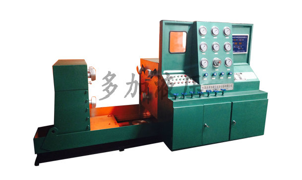
设备全过程由液压驱动、电器控制,对阀门无任何附加影响测试结果的外力,很大程度上提高了工作效率,减轻了劳动强度,是阀门制造企业、使用和检修单位理想的新一代阀门试压检测设备。
DYFJ-A800型阀门试验台工作原理及结构
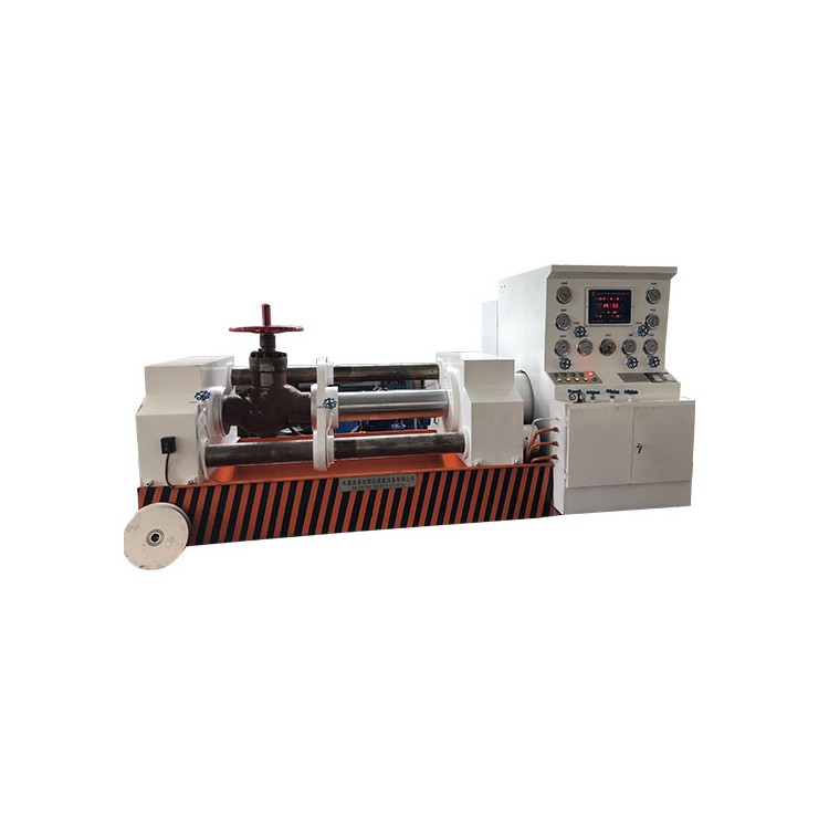
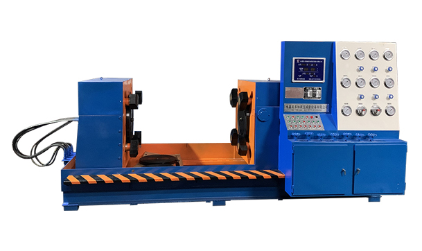
DYFJ-A800型阀门试验台采用阀门法兰定位、活爪夹紧法兰背面的方式进行工作,对阀门测试无任何附加影响测试结果的外力,符合国家规定标准的阀门测试要求。
设备大致分为液动供压系统、电器控制系统、水路循环系统及各项运行装置。
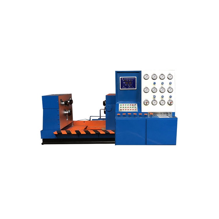
设备为平卧抱压式,左右工作台各有密封盲板密封,左侧工作台设有进退功能机构,由液压油缸直接驱动实现,使阀门密封面受力均匀,压紧可靠。(左)右工作台可以90度翻转,方便进行气密封试验的检查和对阀门密封面密封情况的观察,具有性能良好,结构简单紧凑等特点。

使用操作方法
1、阀门装夹方法
按照设备型号选择公称通径相符合的阀门,开启电源,启动液压系统。左侧移动架退至大于被试阀门长度,活动夹爪径向移动到大于被试阀门法兰外径,夹爪轴向延伸到大于阀门法兰厚度。将阀门法兰面紧贴于左侧工作台试压盲板,对准中心空位置。径向移动夹爪,靠近阀门法兰即可,轴向移动夹爪,使夹爪紧贴阀门法兰背面。此刻阀门应该被左侧装夹系统紧紧的抓牢固定住,确保阀门不会脱落。
左侧移动架往右侧固定工作台前进,被测阀门另外一端紧贴于右侧试压盲板,对准中心空位置。径向移动夹爪,靠近阀门法兰即可,轴向移动夹爪,使夹爪紧贴阀门法兰背面。此刻阀门应该被右侧装夹系统紧紧的抓牢固定住,阀门整体处于水平位置。
2、水压测试方法(双向进水、放水)
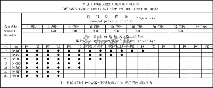
阀门装夹完毕后,参照《夹紧油缸所需压力对照表》将液压夹爪抓紧力增压到所需压力。调整电接点压力表(以25公斤阀门为例,将电接点压力表指针调整至2.5MPa)。打开总进水、左、右进水阀门,关闭进气,放水,放气阀门。启动低压水泵,观察水压表指针移动情况,当指针停止上升,说明阀门内腔已经注满水,启动高压水泵,水压达到电接点压力表设置压力时,高压水泵自动停止,设备进入水压保压状态。
达到保压时间,阀门无任何问题,应先打开放水阀门排除阀门内腔的水压,再取下阀门。
3、气压测试方法(双向进气、放气)
设备自身无配备气源,使用单位需另配气源,使用高压气体时请先咨询厂家。
阀门装夹完毕后(以压力空气为例,一般压力不高于10公斤),打开进水、进气阀门,关闭放水、放气阀门。气压表达到压力至高值时,关闭进水、进气阀门,设备处于保压状态。
达到保压时间,阀门无任何问题,应先打开放气阀门排除阀门内腔的气压,再取下阀门。
使用注意事项及要求
1、安装时应校好设备水平位置或用混凝土固定地脚槽钢。
2、选用46号抗磨液压油(低于0℃应选用防冻46号抗磨液压油),油量不能低于油位计下限。定期检查油位及液压油。使用1年后应清洗油箱,更换液压油。
3、循环水应添加防锈粉,水质变差后应及时换水。
4、设备工作台面应保持干净,被试阀门法兰与试压盲板之间不允许有杂物。
5、试验台各活动部件,要添加润滑油,保持清洁润滑使用。
6、操作人员上岗前需进行专业培训,规范操作,注意安全。


 冀公网安备13010402003046号


