


详情描述
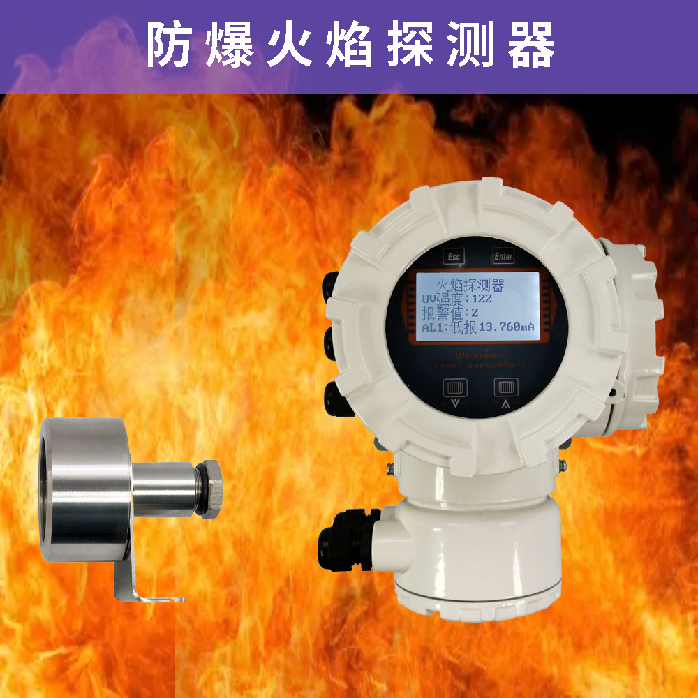
AOFT紫外线火焰探测器(简称探测器)为非编码(继电器输出)感光型探测器,适用于安装在含有ⅡC级T6温度组别的爆炸性气体环境场所,用于火灾发生时易产生明火的火灾探测。本产品结构合理、造型美观、性能可靠、安装方便,是一种可靠性高、抗干扰能力强的火灾探测装置。
紫外火焰传感器(185-260纳米)能够在火警和爆炸点燃的瞬间对紫外线放射作出快速响应(但紫外线放射源如闪电、电弧焊和正面阳光辐射都会使紫外探测器发生错误报警)。探测器的高亮LED可显示探测器的状态,其自动测试功能可保证探测器在任何时候都能充分发挥其功能。

主要技术参数
①、供电电源:24VDC;
②、火焰感应:当检测到火焰时,仪表正常动作;
③、变送输出:4~20mA,电流型变送器输出负载阻抗:<300;
④、通讯输出:带RS485通讯隔离接口;
⑤、报警输出:带一路继电器输出,继电器容量:0.5A/240V AC,阻性;
⑥、报警状态输出:正常工作时,输出4mA±1mA;
报警时,输出12mA±1mA。
试验、安装与接线
1、试验:每只探测器进线口均外引四根导线,用于检验探测器,用户开箱后应尽快做报警试验。将DC24V电源线接在探测器的DC24V电源端子(注意区分正负极性),另外两根线为无源触点。探测器探测范围内无明火时,无源触点间的电阻为无穷大,当探测范围内有明火时,无源触点之间的电阻为零。注:产品外接的四根导线只是用于检验产品用,产品向系统连接时,应将试验用线去掉,采用截面积S≥1.0mm2的通用电缆连接,否则,防爆探测器将失去防爆性能。
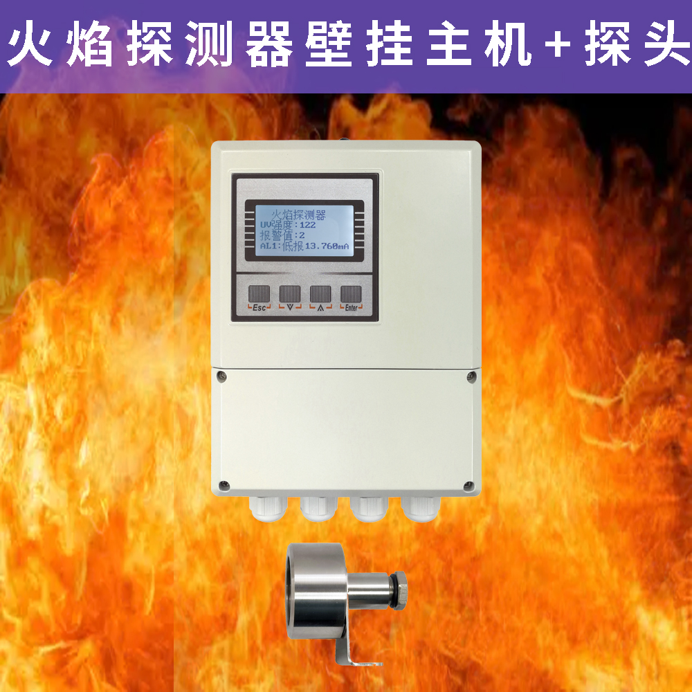
2、安装:将探测器的固定架安装在墙壁上,再将防爆外壳连接在固定架上.电缆的引入装置:采用封口螺帽压紧密封圈结构。
3、接线:松开探测器的固定螺钉,打开接线腔,将电缆线分别接在接线端子上。连线接好后,将盖与体装好。

调试
警告:请待全部探测器都安装完毕后再接通电源。
1、探测器安装结束后或每次定期维护保养后须进行测试。
2、测试内容:
模拟火警:探测器接通电源后,用点燃的的打火机、蜡烛等紫外辐射光源接近探测器,探测器应报火警,探测器的火警指示灯点亮,输出触点闭合。
3、测试结束后,用切断电源的方法复位探测器,并通知有关管理部门系统恢复正常。
询价单


 冀公网安备13010402003046号