


- AllProduct Category
-
Water Level Sensing
Traffic Sensing
Weighing Instrument
Analytical Instruments
Flow Meters
Pressure Gauges
Material Level Instrument


详情描述
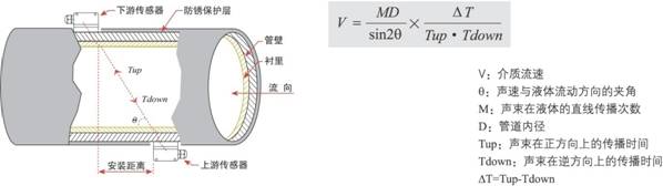
I. Working Principle
AO-100 SeriesUltrasonic Flow Meter/Ultrasonic flow meters utilize the principle of low voltage and multi-pulse time difference, employing digital detection technology with dual-balance signal differential transmission and reception to measure the sound wave transmission time in both upstream and downstream directions. Flow velocity is calculated based on the time difference. They feature good stability, minimal zero-point drift, high measurement accuracy, wide measurement range, and strong anti-interference capability.
When ultrasonic beams propagate through a liquid, the liquid's flow will cause minor changes in the propagation time, and this change in propagation time is directly proportional to the liquid's flow rate. At zero flow, the time required for both sensors to emit and receive sound waves is exactly the same (a technique to measure zero flow can be actually implemented); when the medium flows, the transmission time of sound waves in the upstream direction is greater than that in the downstream direction. This relationship is consistent with the following expression:
Content | Technical Features | Note |
Measurement Accuracy | Flow meter/Heat meter: better than ±1.0%; Water meter: better than ±2.0%; Heat meter: meets EN1434 standard | See product description |
Repeatability | Better than ±0.2% or ±0.5% | |
Fluid Direction | Bidirectional measurement, capable of measuring positive, negative, and net cumulative volume | |
Flow Rate Range | 0~± 32m/s | |
Measurement Medium | Water, wastewater, seawater, alcohol, various oils, etc., single, uniform, stable liquids capable of conducting ultrasonic waves | |
Applicable pipe materials | Carbon steel, stainless steel, cast iron, cement, copper, PVC, aluminum, etc., uniform and dense piping, lined if allowed | External mounted sensors are not suitable for cement pipes. |
Fluid Temperature | ≤ 160℃ | See product description |
Fluid Turbidity | ≤10000ppm and low bubble content | |
Display | Instant flow, heat, flow rate, cumulative volume, signal status, and more displayed in full Chinese. | |
Output Interface | 4-20mA, Relay, OCT, RS232, RS485 output options | |
Input Interface | 4-20mA analog input | |
Additional Features | Cumulative Days, Months, Years; Power On/Off Management Function; Self-Diagnosis Function for Operating Status | |
Communication Protocol | MODBUS Protocol, M-BUS Protocol, and Aotele Extension Protocol |
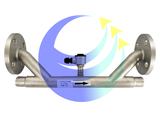
Two, Integrated Ultrasonic Flow Meters
The AO-100Y integrated ultrasonic flow meter is a tube segment-type ultrasonic flow meter developed using a low-power single-chip microcontroller. This product resolves the issue of reduced measurement accuracy caused by errors during installation, such as human error or inaccurate pipe parameters in externally mounted and inserted sensors. It features high accuracy, wide measurement range, low cost, simple installation, minimal pressure loss, and no moving mechanical parts. The launch of this product changes the notion that ultrasonic flow meters can only be installed in a split configuration, marking the future direction of ultrasonic flow meter development.
Measurement Accuracy: Better than ±1%
2. Measurement Cycle: Every 2 seconds (500ms)
3. Operating Voltage: Selectable 24V or AC220V
4. Flow Rate Range: 0 to 32 m/s
5. Display: Local 2x10 Chinese character backlit display
6. Signal Input: 1 channel 4-20mA analog input, accuracy 0.1%, capable of inputting signals such as temperature and pressure.
7. Signal Output: 1 channel 4-20mA analog output, accuracy 0.1%
2-channel programmable OCT output
Scheduling Print Output Expansion Feature
Universal Serial Bus RS232/Rs485 Dual Interface
8. Connection Type: Optional Flange or Quick-Connect (Sanitary Type)
9. Operation: 16-key touch keyboard
10. Data Storage: Automatically records the cumulative traffic and work logs for the last 128 days, 64 months, and 5 years.
Automatically record the time and flow of the first 32 power-on, power-off, and power failure events.
11. Power Failure Protection: Data retention for up to 100,000 hours without power loss
12. Medium Temperature: -40℃ to 160℃
13. Protection Level: IP65
14. Electrical Interface: M20×1.5
15. High power consumption: 1.2W
Section 3: Flange Mechanical Dimensions Table
Nominal Bore Size DN(mm) | Rated Pressure (MPa) | π-shaped pipe section external dimensions (mm) | Standard Pipe Segment Dimensions (mm) | Flange Dimensions (mm) | |||||
L1 | H1 | L2 | H2 | D | D1 | D2 | N-Φ | ||
15 | 2.5 | 320 | 136 | 95 | 65 | 46 | 14×4 | ||
20 | 360 | 142 | 105 | 75 | 56 | 14×4 | |||
25 | 390 | 151 | 115 | 85 | 65 | 14×4 | |||
32 | 450 | 157 | 140 | 100 | 76 | 18×4 | |||
40 | 500 | 169 | 150 | 110 | 84 | 18×4 | |||
50 | 1.6 | 200 | 260 | 165 | 125 | 99 | 18×4 | ||
65 | 200 | 280 | 185 | 145 | 118 | 18×4 | |||
80 | 225 | 295 | 200 | 160 | 132 | 18×8 | |||
100 | 250 | 314 | 220 | 180 | 156 | 18×8 | |||
125 | 250 | 347 | 250 | 210 | 184 | 18×8 | |||
150 | 300 | 372 | 285 | 240 | 211 | 22×8 | |||
200 | 350 | 430 | 340 | 295 | 266 | 22×12 | |||
250 | 450 | 489 | 405 | 355 | 319 | 26×12 | |||
300 | 500 | 543 | 460 | 410 | 370 | 26×12 | |||
350 | 550 | 599 | 520 | 470 | 429 | 26×12 | |||
400 | 600 | 653 | 580 | 525 | 480 | 26×16 | |||
450 | 700 | 708 | 640 | 585 | 548 | 30×20 | |||
500 | 800 | 771 | 670 | 620 | 585 | 25×20 | |||
600 | 1000 | 884 | 780 | 725 | 685 | 30×20 | |||
700 | 1100 | 964 | 860 | 810 | 775 | 24×25 | |||
800 | 1200 | 1072 | 975 | 920 | 880 | 24×30 | |||
900 | 1300 | 1172 | 1075 | 1020 | 980 | 24×30 | |||
1000 | 1400 | 1287 | 1175 | 1120 | 1080 | 28×30 | |||
IV. Live Socket (Sanitary Type) Mechanical Dimensions Table
Nominal Bore DN(mm) | Rated Pressure (MPa) | 活接式 external dimensions | Material | |||
L | H | D | C | |||
25 | 4.0 | 300 | 282 | 51 | 19 | Stainless Steel |
40 | 300 | 300 | 74 | 23 | ||
50 | 300 | 310 | 84 | 24 | ||
65 | 350 | 330 | 100 | 28 | ||
80 | 400 | 345 | 114 | 30 | ||
100 | 450 | 365 | 128 | 31 | ||
Section 5: Battery-Powered
Battery-powered integrated ultrasonic flow meters are ultra-low power consumption ultrasonic flow meters that can operate for extended periods using a 3.6V lithium battery. They feature high measurement accuracy, maintenance-free operation, and no need for manual handling, making them particularly suitable for field or urban pipeline metering.
1. Measurement accuracy exceeds ±1%
2. Repeatable within ±0.2%
3. Measurement cycle: 1 second (1s)
4. Flow Rate Range: 0 ~ 32 m/s
5. 3.6V lithium-ion battery with over two years of continuous operation
6. Locally sourced 96-segment ultra-low power LCD display:
Positive and Negative Accumulated Volume, Instantaneous Flow Rate, Flow Velocity, Accumulated Working Time, Date, Working Status, and Error Codes
Battery power, ultrasonic signal strength and signal quality
7. 4-20mA Analog Output (Two-Wire System)
8. RS232 (Power Theft Output), RS485 (requires external 5V) Data Output
9. MODBUS and Aotek Extended Communication Protocol
10. Measurable medium temperature range: -40℃ to 160℃
11. Internal dual-button, magnetic rod operation
12. Optional viewing modes: Eye-level, downward view
13. Flanges and Swivel (Sanitary) Connections Available
14. Protection Class: IP68
15. Explosion-proof Grade: EXdⅡCT6
16. Power Consumption: Average power consumption of DN100 pipe diameter is 1.65 mW
Section 6: Flanged Mechanical Dimensions Table
Nominal Bore Size DN(mm) | Rated Pressure (MPa) | π-section pipe segment outer dimensions (mm) | Standard Tube Section Dimensions (mm) | Flange Size (mm) | |||||
L1 | H1 | L2 | H2 | D | D1 | D2 | N-Φ | ||
15 | 2.5 | 320 | 132 | 95 | 65 | 46 | 14×4 | ||
20 | 360 | 138 | 105 | 75 | 56 | 14×4 | |||
25 | 390 | 147 | 115 | 85 | 65 | 14×4 | |||
32 | 450 | 153 | 140 | 100 | 76 | 18×4 | |||
40 | 500 | 165 | 150 | 110 | 84 | 18×4 | |||
50 | 1.6 | 200 | 234 | 165 | 125 | 99 | 18×4 | ||
65 | 200 | 254 | 185 | 145 | 118 | 18×4 | |||
80 | 225 | 268 | 200 | 160 | 132 | 18×8 | |||
100 | 250 | 287 | 220 | 180 | 156 | 18×8 | |||
125 | 250 | 315 | 250 | 210 | 184 | 18×8 | |||
150 | 300 | 345 | 285 | 240 | 211 | 22×8 | |||
200 | 350 | 403 | 340 | 295 | 266 | 22×12 | |||
250 | 450 | 462 | 405 | 355 | 319 | 26×12 | |||
300 | 500 | 516 | 460 | 410 | 370 | 26×12 | |||
350 | 550 | 572 | 520 | 470 | 429 | 26×12 | |||
400 | 600 | 626 | 580 | 525 | 480 | 26×16 | |||
450 | 700 | 682 | 640 | 585 | 548 | 30×20 | |||
500 | 800 | 745 | 670 | 620 | 585 | 25×20 | |||
600 | 1000 | 858 | 780 | 725 | 685 | 30×20 | |||
700 | 1100 | 938 | 860 | 810 | 775 | 24×25 | |||
800 | 1200 | 1046 | 975 | 920 | 880 | 24×30 | |||
900 | 1300 | 1146 | 1075 | 1020 | 980 | 24×30 | |||
1000 | 1400 | 1261 | 1175 | 1120 | 1080 | 28×30 | |||
Section 7: Live-Connector (Sanitary Type) Mechanical Dimensions Table
Nominal Bore Size DN(mm) | Rated Pressure (MPa) | 活接式 Outer Diameter | Material | |||
L | H | D | C | |||
25 | 4.0 | 300 | 178 | 51 | 19 | Stainless Steel |
40 | 300 | 196 | 74 | 23 | ||
50 | 300 | 206 | 84 | 24 | ||
65 | 350 | 226 | 100 | 28 | ||
80 | 400 | 241 | 114 | 30 | ||
100 | 450 | 261 | 128 | 31 | ||
Medium to large diameter pipe sections

Small diameter pipe sections:
询价单


