


- AllProduct Category
-
Water Level Sensing
Traffic Sensing
Weighing Instrument
Analytical Instruments
Flow Meters
Pressure Gauges
Material Level Instrument


详情描述
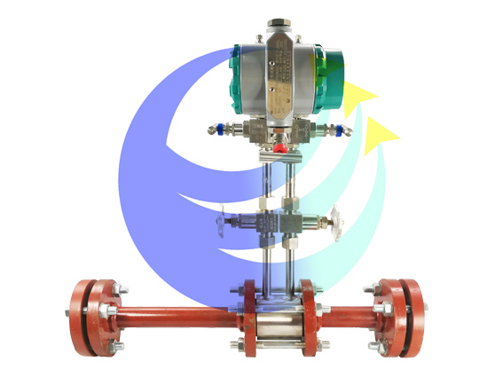
I. Overview and Working Principle
Fluids within pipelines, as they pass through throttling devices, experience a local contraction at the throttling element, which increases velocity and decreases static pressure. This results in a pressure drop, or differential pressure, before and after the throttling element. The greater the flow rate of the medium, the larger the pressure differential across the throttling element. Therefore, flow rate can be measured by assessing the differential pressure. This method is based on the laws of conservation of energy and continuity of flow. However, the magnitude of the pressure differential is not solely determined by flow rate but also by various other factors, such as the type of throttling device or the physical properties of the flowing medium within the pipeline, like density and viscosity, which can cause different pressure differentials at the same flow rate.
Throttle devices are differential pressure generating devices used to measure flow rates. When paired with various differential pressure gauges or transmitters, they can measure the flow rates of various fluids in pipes: throttle devices include ring chambers, orifice plates, nozzles, and classical Venturi tubes.
Throttling devices are used in conjunction with differential pressure transmitters to measure the flow of liquids, steam, and gases. They are widely applied in industries such as petroleum, chemical, metallurgy, power, and light industry.
II. Main Technical Characteristics
1. Angle Take-Pressure Standard Orifice Plate, suitable for pipe diameters from 50mm to over 1000mm. The Reynolds Number Red range is 5×10^3 to 10^7. The diameter ratio is β (ranging from 0.22 to 0.80).
Recommended Red min value for the Reynolds number of pressure tapping standard orifice plates.
β | Red min | β | Red min | β | Red min |
0.22 | 5.00×10³ | 0.525 | 2.13×10⁴ | 0.625 | 6.27×10⁴ |
0.250 | 8.00×10³ | 0.450 | 2.49×10⁴ | 0.650 | 7.16×10⁴ |
0.275 | 9.00×10³ | 0.475 | 2.87×10⁴ | 0.675 | 8.21×10⁴ |
0.300 | 1.30×10⁴ | 0.500 | 3.29×10⁴ | 0.700 | 9.48×10⁴ |
0.325 | 1.70×10⁴ | 0.525 | 3.75×10⁴ | 0.725 | 1.11×10⁵ |
0.350 | 1.90×10⁴ | 0.550 | 4.27×10⁴ | 0.750 | 1.32×10⁵ |
0.375 | 2.00×10⁴ | 0.575 | 4.85×10⁴ | 0.775 | 1.59×10⁵ |
0.400 | 2.00×10⁴ | 0.600 | 5.51×10⁴ | 0.800 | 1.98×10⁵ |
If the orifice plate with standard pressure tapping is used at Reynolds numbers higher than those listed in the table, the change in flow coefficient due to flow variation does not exceed 0.5% compared to the actual value.
2. Angle Take-Pressure Standard Nozzle: Suitable for pipe diameters ranging from 50mm to 500mm, with a Reynolds Number (Red) range of 2×10^4 to 2×10^6, and a diameter ratio β (within the range of 0.32 to 0.80).
Recommended Red min value for the Reynolds number of a standard pressure tap angle connector
β | Red min | β | Red min | β | Red min |
0.320 | 4.05×10⁴ | 0.500 | 4.94×10⁴ | 0.675 | 4.66×10⁴ |
0.350 | 3.93×10⁴ | 0.525 | 5.22×10⁴ | 0.700 | 3.42×10⁴ |
0.375 | 3.95×10⁴ | 0.550 | 5.49×10⁴ | 0.725 | 2.00×10⁴ |
0.400 | 4.04×10⁴ | 0.575 | 5.69×10⁴ | 0.750 | 2.00×10⁵ |
0.425 | 4.19×10⁴ | 0.600 | 5.78×10⁴ | 0.775 | 2.97×10⁵ |
0.450 | 4.40×10⁴ | 0.625 | 5.69×10⁴ | 0.800 | 5.19×10⁵ |
0.475 | 4.66×10⁴ | 0.650 | 5.35×10⁴ |
询价单


