





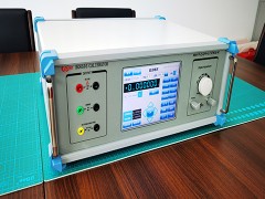


The U-II type is a type of heat dissipation pipe that is suitable for both steam heating systems and hot water heating systems. Its inlet and outlet joints are on the same side, and the inlet and outlet pipes are connected by U-shaped elbows. This meets certain special installation requirements, such as the need for one end of the heat dissipation pipe to be against a wall or other obstacles.
The finned tubes are made by winding 10 × 0.2mm corrugated copper strips around a diameter of 16 × 1mm copper tube, forming a spiral shape with three different pitch sizes of 3.2mm - "R", 4.2mm - "M", and 6.5mm - "T". The "R" pitch has a small pitch size but a large heat dissipation area, resulting in a large heat dissipation capacity; The "M" type has a larger spacing, resulting in lower heat dissipation and air resistance; The "T" spacing is large and suitable for situations where the steam pressure is high and the air temperature rise is low.
The U-II type heat dissipation tube has various combinations of different surface tube lengths, tube numbers, row numbers, and fin spacing, with a total of 765 sizes and specifications.
After the winding of the finned tube is completed, the surface is dipped in tin alloy to ensure a tight contact between the fins and the tube, and to achieve a beautiful and corrosion-resistant effect.
The connection between the finned tube and the intake and return main pipe is made by brazing, and other process details are strictly required and carefully considered to ensure good performance, durability, easy installation, and cost-effectiveness of the radiator.
The U-II numbering method is:
Model one row number (spacing code) 3.2- number of surface tubes - length of surface tubes (inches).
If two rows are used, with a spacing of 3.2mm, 21 surface tubes, and a tube length of 60 inches, it is UII-2 (R) -21-60.
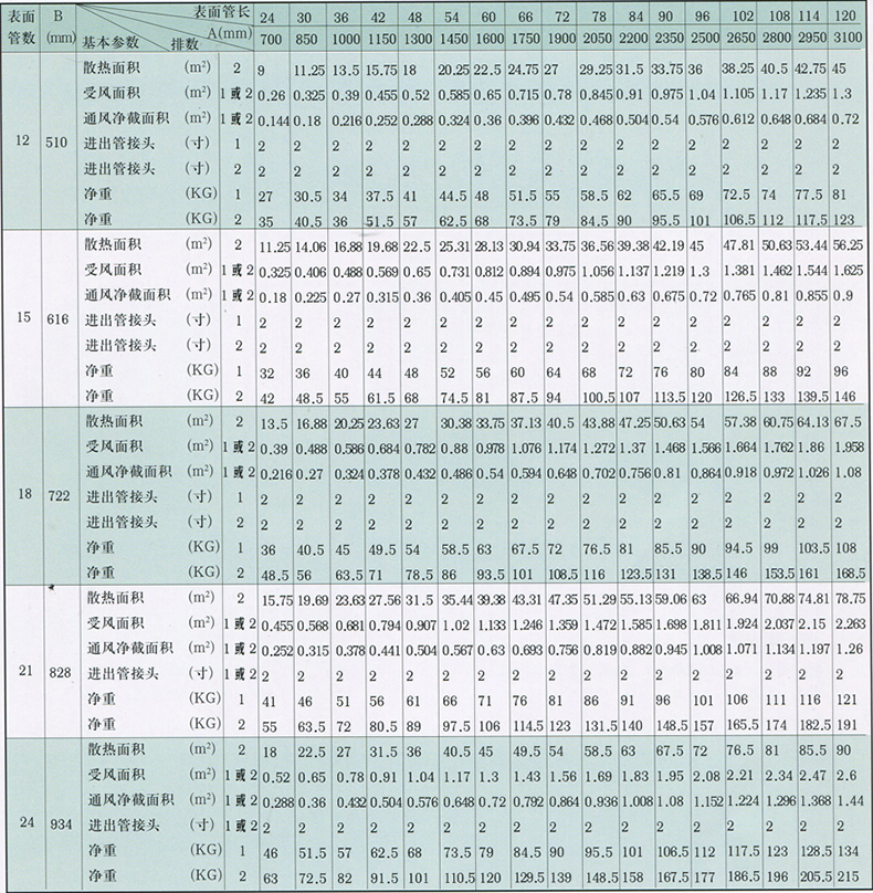
The surgical parameters of U-II type are shown in the table
Technical parameters of U-II type heat dissipation pipe
Note:
1. The heat dissipation area 2R in the table represents the fin data. In other cases, the following constants can be used for conversion:
1R - fin heat dissipation area=2R - fin heat dissipation area × 0.5 2M - fin heat dissipation area=2R - fin heat dissipation area × 0.77
1M - fin heat dissipation area=2R - fin heat dissipation area × 0.385 2T - fin heat dissipation area=2R - fin heat dissipation area × 0.54
1T - fin heat dissipation area=2R - fin heat dissipation area × 0.27
2. The ventilation net section grade in the table is calculated based on the spacing between sections. If it is other spacing, it can be converted using the following constants:
M spacing ventilation net cross-sectional area=R spacing ventilation net cross-sectional area × 1.015 T spacing ventilation net cross-sectional area=R spacing ventilation net cross-sectional area × 1.035
3. The net weight in the table refers to the tube weight of 1R fins and 2R fins. If it is for other spacing, it can be converted using the following constants:
1M - Net weight of finned tubes=Net weight of tubes with a spacing of 1R x 0.94 2M - Net weight of tubes with fins=Net weight of tubes with a spacing of 2R x 0.92
1T - Net weight of finned tube=1R net weight of one-sided tube x 0.85 2T - Net weight of finned tube=2R net weight of finned tube x 0.78