







The decelerator test bench consists of two parts: the mechanical section (power dynamometer) and the measurement and control system (cabinet).
The mechanical part consists of a drive motor, input torque-speed sensor, measured reducer, output torque-speed sensor, load motor, variable frequency feedback system, cast iron platform, and fixture connection parts.
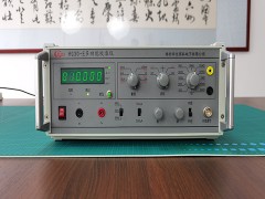
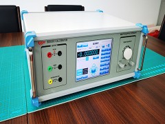
The testing (container) system consists of various data collection instruments, industrial control computers, monitors, testing software, alarm communication protection devices, and various electrical components.
Testing (Cabinet) System Working Principle: During testing, the controller controls the loader until the reducer's power reaches the rated value. Due to the torque change, the torque sensor generates two different signals, which are displayed by the matching measuring instrument as the input and output torques T, rotational speeds n, and power P. The temperature measuring instrument displays the real-time temperature θ through different electrical signals generated by the temperature sensor due to temperature changes. All instruments are collected and processed by the test software via the network port (TCP/IP) to determine the efficiency η (η = P_out/P_in) and temperature rise Δθ (θ_final - θ_initial) of the reducer. This system meets the precise measurement requirements for the input torque, speed, and power; output torque, speed, power, and efficiency; as well as environmental temperature, oil temperature, and temperature difference. The test results can also be printed and stored in data and curve formats.