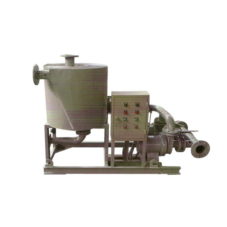


YSL type transformer with spiral plate oil-water cooler
Structural Features and Working Principle
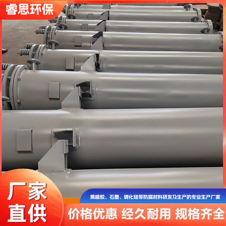
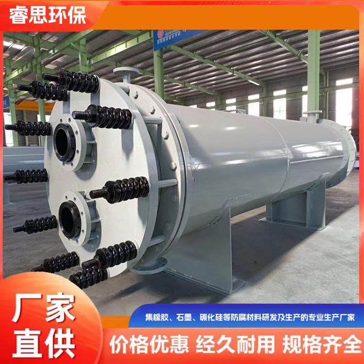
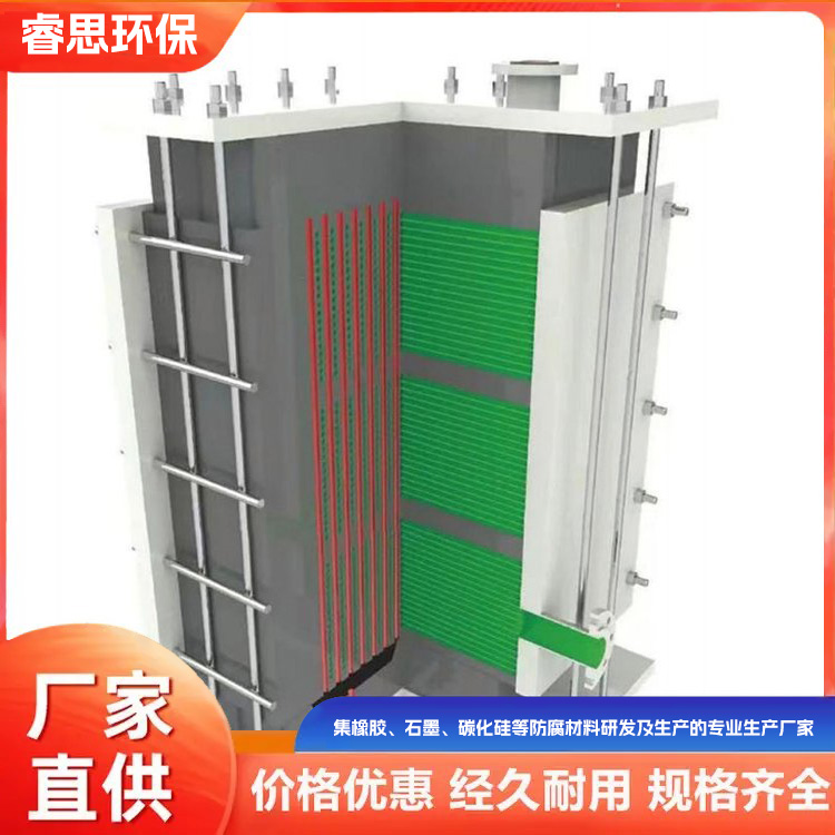
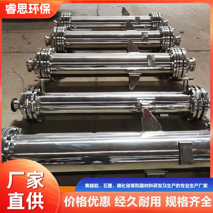
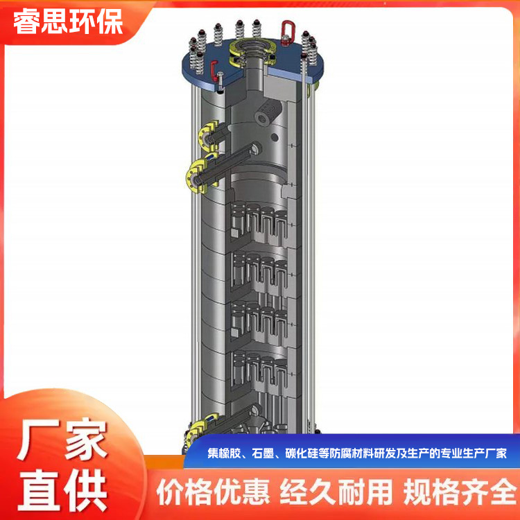
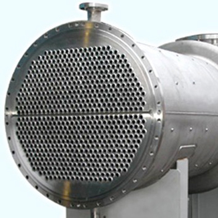
Spiral plate coolers are widely used heat exchange devices known for their high heat transfer efficiency and low pressure loss. They offer stable and reliable operation, compact structure, and cost-effectiveness. Currently, they are extensively applied in petrochemical refrigeration, organic chemical food, machinery, metallurgy, and other industrial sectors. The spiral plate oil-water cooler is made of two sheets, 2-3mm thick, rolled into two uniform spiral channels. Joints are welded at the beginning and end of the two spiral channels, as well as along the upper, lower, and tangential directions of the spiral body.
Tubes and flanges, with two channels each containing a loaded liquid (oil and water) in a full countercurrent state for heat exchange. The cooling area is the sum of the extended length of the two steel plates multiplied by the width of the steel plates. To enhance the rigidity of the steel plates and increase the critical pressure of the helix, fixed spacing columns with a certain density are welded on the same phase surface of the two steel plates. This also increases the turbulence of the fluid, enhances the Reynolds number, and improves the heat transfer efficiency.
Due to the uniform curvature of the spiral channels, there is no significant redirection of fluid, resulting in lower resistance and no dead corners. To enhance heat exchange efficiency, the fluid typically flows at a higher velocity within the channels, which prevents clogging by debris and the channel itself has an auto-cleaning function. Additionally, both spiral channels are equipped with exhaust (liquid) ports for ease of operation and can also be used for sampling and testing.
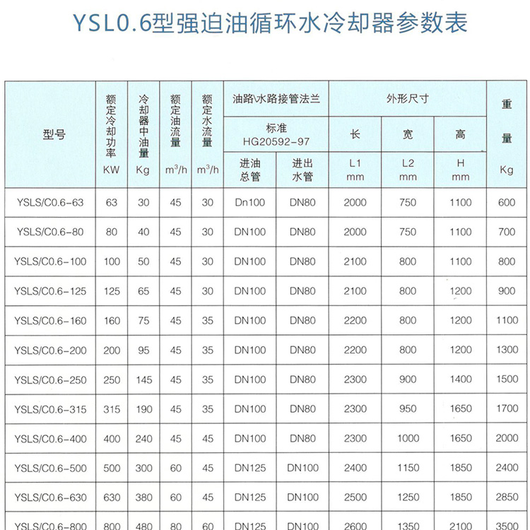
YSL0.6 Transformer with Strong Cooling Type Parameters

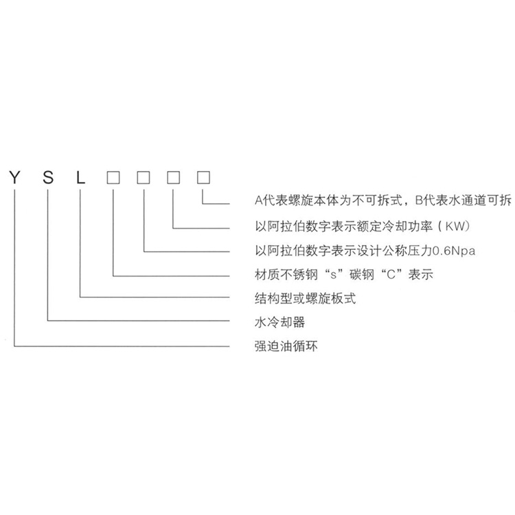
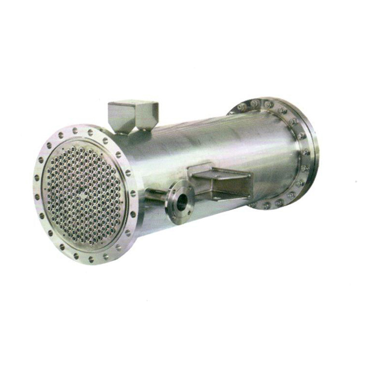
YSLS-0.6-160-A is a non-disassemblable helical plate cooler, made of acid-resistant stainless steel, with a design pressure of 6Mpa. It features a heat exchange area of 16m² and a cooling power of 160KW.
YSLC-0.6-200-B is a removable spiral plate cooler with water channels, made of carbon steel, and designed for a pressure of 0.6 Mpa. The heat exchange area is 20 m² (with a cooling power of 200 kW).
Product Features
1. High thermal efficiency
Overall heat transfer coefficient up to 3300 Kcal/m³2.h. C has superior heat transfer efficiency over YF (air-cooled) spiral plate coolers. The heat exchange coefficient is 1-3 times that of traditional tube bundles, thereby saving energy and offering good economic performance.
2. Less heat loss
This oil cooler has a compact structure with minimal占地面积 and exposed surface area. No insulation is required if the ambient fluid flows from the outer edge to the center of the oil cooler.
3. Durable structure
The oil and water channels are rolled into a single plate, sealed with welding, ensuring that oil and water do not mix during heat exchange, thereby guaranteeing the transformer's safe operation.
4. Self-cleaning function
This oil cooler can appropriately increase the liquid flow rate while ensuring minimal drop in channel pressure, thereby enhancing heat transfer efficiency. The liquid flows in a spiral pattern, featuring an automatic cleaning function, which reduces dirt accumulation. This results in less downtime for maintenance, saving on repair costs.
Technical Specifications
1. Nominal pressure is specified as an additional 6MPa and 1.0MPa (Note: Refers to the working pressure the single channel can withstand; the test pressure at our factory is 1.25 times the design pressure).
2. Operating Temperature Range: The allowable temperature range for carbon steel heat exchangers is 1°C to +200°C, while for stainless steel heat exchangers, it is 1°C to +900°C. The allowable pressure range for temperature fluctuations in carbon steel heat exchangers is as specified in the relevant operational regulations.
3. When selecting equipment, appropriate process calculations should be used to determine the fluid's optimal operating state, ensuring the fluid within the oil cooler passages achieves turbulent flow (typically with a liquid velocity of ≥1 m/sec.).
4. Users can select different materials based on various working conditions. In this manual, the symbol C represents carbon steel Q235A, while the symbol S represents stainless steel SUS304, 321, and 316L.
5. When using a single cooler, it is generally operated with two oil pumps, one in use and the other as a backup. If a single unit does not meet the operational requirements, multiple units can be used in combination, but the configuration must comply with the following regulations:
(1) Parallel Assembly: Limited to heat exchangers of the same specification.
(2) Series Assembly: The plate spacing and channel width of the heat exchanger should be uniform.
(3) Mixed Combination: Parallel connection in one channel, series connection in another, limited to heat exchangers of the same specification.
6. Installation Types: Horizontal and Vertical. To ensure all materials are thoroughly drained after parking to prevent cracking and damage during winter, the horizontal type is commonly used.
7. The orientation of the oil cooler inlet is as per the product's factory drawings, with the nominal diameter of the inlet selected from the table. If the customer has special requirements, they may negotiate with our technical department. After the customer selects the specifications, they may write to request a reference drawing for the external dimensions.
YSL0.6 Transformer Oil Cooler Selection and Installation
1. Oil coolers and selection and usage
Currently, our factory has a series of models for oil coolers used in electric furnace transformers (refer to Table 1). The cooling medium is water, and the incoming water temperature must not exceed 30°C; otherwise, it will affect the cooling efficiency. If required (an electric contact and a thermometer can be installed at the inlet, and external monitoring is available.), please specify at the time of ordering.
The cooling water quality should meet the following criteria:
Turbidity ≤ 50 mg/L, Calcium Carbonate 100-200 mg/L, Calcium Sulfate 1500-2000 mg/L, Iron 0.1 mg/L, Manganese 0.1 mg/L, Chloride ions (Ce) ≤ 25 mg/L, pH = 7. Cooling water saturation index 1 > 0 (if 1 < 0, it may cause corrosion to stainless steel). The cold source medium is clean recycled water; if river water is used, a filter must be added to prevent other impurities from entering the cooler, causing blockages and affecting cooling efficiency. Softening the cooling water before use is recommended to avoid scale buildup and impact cooling performance. Hard water from deep wells must be softened. Once scaling occurs in the cooler's water channels, a boiler descaling company can be hired for cleaning, with the duration depending on water quality and cooling efficiency. Those with the means can use boiler descaling agents for cleaning.
The method is as follows:
Dissolve the boiler descaling agent (powder) at a ratio of 0.5% in clean water and circulate it for several hours. Then, open the drain valve (below the cooler's inlet pipe) and flush it clean with water. For units with extremely poor water quality and no cleaning facilities, an optional removable cooling tube (Type B) can be used. This allows for the cleaning of the water passage, but it comes at a higher equipment cost.