


1.1 Overview of Functions
The system is a self-developed one, primarily functioning by deeply integrating welding processes, importing 3D models, and then using a visual system to locate the weld seams of the entire component. Based on the actual contours in the model, it automatically generates welding programs.
Software is deployed on PC systems, which can be placed anywhere. Remote control is achievable through the TCP/IP protocol, allowing direct operation of on-site equipment for welding from the office.
1.1.1 The system can operate a double shift (8 hours per shift) every day while maintaining stable accuracy.
1.1.2 The design drawings for the workstations have undergone repeated verification and simulation design. The design strength of each component is reliable, and assembly and maintenance are convenient. Under the premise of ensuring functionality, it also guarantees the aesthetic appearance.
1.1.3 All externally sourced components of the work station equipment are provided by renowned manufacturers in the industry, with all processed parts undergoing rigorous quality control, meeting strength standards, superior performance, and smooth operation.
1.1.4 The measurement units for parts, instruments, and all technical drawings of workstations equipment are in accordance with the National Standard (GB); the design, manufacturing, and materials used for all instruments and components shall comply with ISO and IEC standards or equivalent standards.
1.1.5 Workstation components are made from high-quality materials, featuring reliable series of mechanical and electrical elements.
1.1.6 The robot front end is equipped with collision sensors, which can stop the machine in time to protect against collisions. Additionally, the system can be configured with an automatic wire trimming system and an automatic dust removal system as per requirements.
1.1.7 Workstation visual interaction, 3D numerical model-driven, intelligent welding path planning, visual scan path correction, matching parameters, and automatic creation of welding programs with process library.
1.1 Structural Types and Recommended System Operation
1.1.1 The H-beam crane beams and reinforced plate structures use a one-button start operation method with dedicated H-beam machinery, requiring minimal human intervention, high work efficiency, and allowing operators to manage multiple machines.
1.1.2 H-shaped steel columns, roof beams, internal stiffening plates of box structures, and products with a variety of structural types, utilize a visual human-machine interaction approach for operation, allowing operators to control multiple machines.
1.1.3 Bridge plates, large box-type partition panels, etc., due to longer weld seams and a limited number of weld types, utilize model-driven welding with minimal manual intervention, resulting in high welding efficiency and allowing operators to manage multiple machines.
1.1.4 The Ketai Intelligent System is a complete system that supports all the aforementioned working modes. Choose the appropriate modules based on actual usage requirements to enhance production efficiency.
MES System
1.1.5 System Features:
a) Share factory model data based on Internet technology.
b) Process-oriented production management, which incorporates every aspect of the production process into the workflow for management
c) Integrate and enhance the overall efficiency of project operations, with real-time, dynamic, and authenticity to achieve full participation in management
d) Process technology, departments, groupings, and permissions can be fully customized
e) Process flow information is implemented in real-time push
f) Schedule production rhythmically automatically
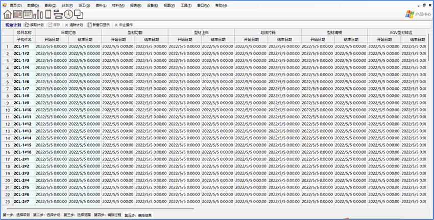
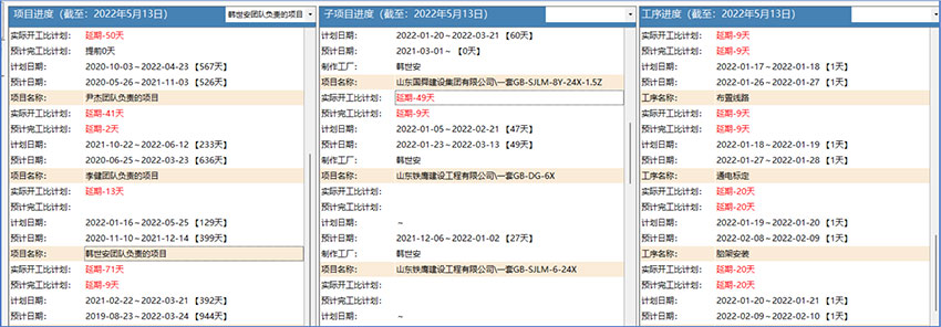
1.1.6 Planning Module: Prior to the implementation of production tasks, Ketai MES automatically schedules plans based on project requirements and the production rhythm of each workshop and work station, generating daily work plans for each station and the corresponding components.
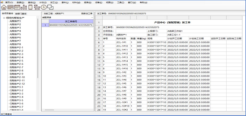
Dispatch Module: Automatically schedules plans based on project requirements and the production rhythm of each workshop and work station, generating specific work tasks.
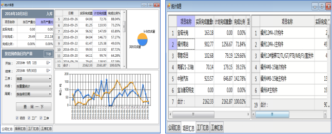
Statistical Module: Allows for querying overall company data, project statistics, factory-wise statistics, and process-wise statistics.
2. Project Proposal
2.1 Product Types
2.1.1 Structural Dimensions
Serial Number | Product | Highness | Width | Length (for dual machine operation) |
1 | H-beam | Flap height ≤ 0.8m | ≤1.2m | ≤12m |
2 | Other Products | Stile height ≤ 0.5m | ≤1.2m | ≤12m |
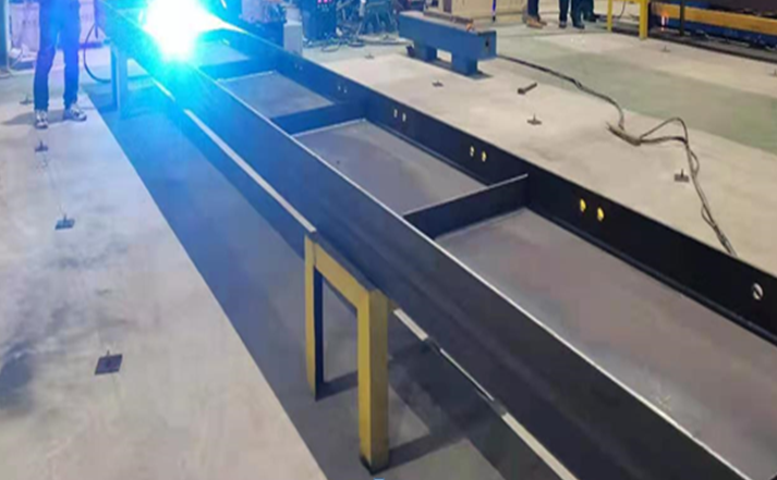
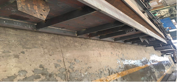
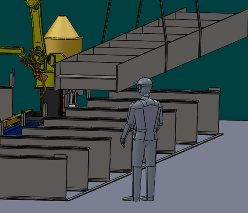
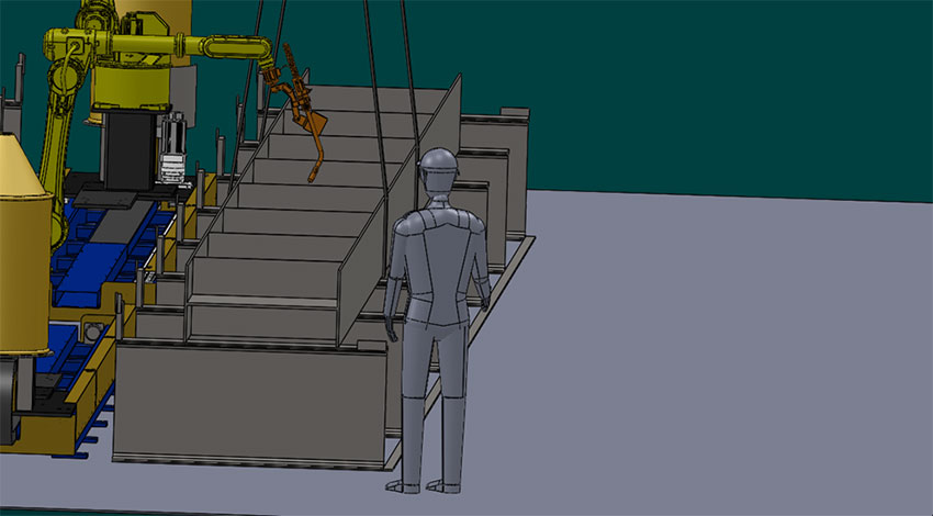
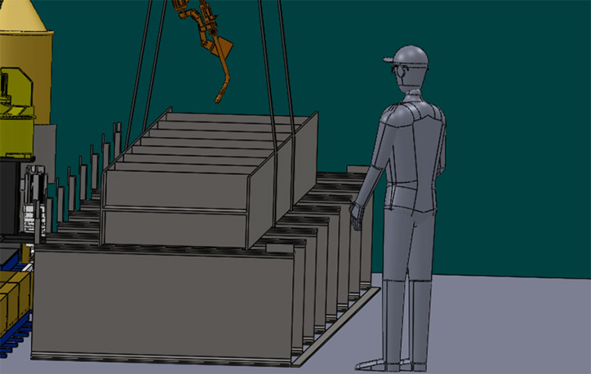
2.1.2 Typical Product Photos for Users
2.1 Global Layout Diagram
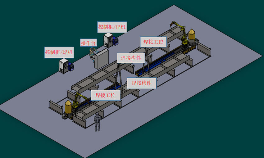
Layout elevation
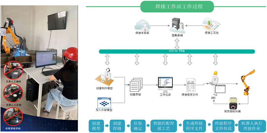
Process Workflow (Model-Driven Approach)
2.2.1 Manually or by conveyance chain, transfer the components to be welded to the worktable, near the positioning point P
2.2.2 Operators, simultaneously or in advance, rotate the model uniformly based on component numbers and placement methods, and create nodes.
2.2.3 If the placement deviation is too large, use a camera to identify component positioning at point P first.
2.2.4 If the placement is close, the operator can directly load the model and initiate the scanning (at this time, the operator can hoist another component onto the second set of equipment racks or another work station on this equipment, and perform the aforementioned operation)
2.2.5 After scanning is completed, the system initiates welding
2.2.6 The entire assembly is焊接完毕,then transferred to the next work station.
2.2.7 The operator can control multiple sets of equipment with this operation.
2.2.8 If there is no component model, equipment welding can be operated using a visual interaction method. After the components are placed on the rack, the operator takes photos of the welding sections with a camera, matches the process, and initiates scanning welding. Compared to model-driven operations, the operator's workload increases.