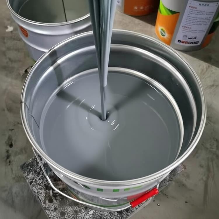


A device that enables convection and uniform mixing of liquid and gas media. The type, size, and speed of the stirrer have an impact on the distribution of stirring power between overall flow and turbulent pulsation. Generally speaking, the power distribution of a turbine agitator is advantageous for turbulent pulsation, while a propeller agitator is advantageous for overall flow. For the same type of agitator, under the same power consumption conditions, large-diameter and low-speed agitators mainly consume power for overall flow, which is beneficial for macroscopic mixing. A small diameter, high-speed mixer mainly consumes power through turbulent pulsation, which is beneficial for micro mixing. The amplification of the mixer is a complex issue related to the process, and so far it can only be amplified through step-by-step experience. Based on the amplification criteria obtained, it can be extrapolated to industrial scale.
Viscosity refers to the impedance ability of a fluid to flow, defined as the magnitude of the required shear stress per 1cm2 plane when a liquid flows at a speed of 1cm/s, known as dynamic viscosity, measured in Pa · s. Viscosity is a property of fluids. When fluid flows in pipelines, there are three states: laminar flow, transitional flow, and turbulent flow. These three flow states also exist in mixing equipment, and one of the main parameters that determines these states is the viscosity of the fluid. In the mixing process, it is generally considered that the fluid with viscosity less than 5Pa/s is a low viscosity fluid, such as water, castor oil, caramel, jam, honey, heavy oil of lubricating oil, low viscosity lotion, etc; 5-50 Pa/s is a medium viscosity fluid, such as ink, toothpaste, etc; High viscosity fluids with a flow rate of 50-500Pa/s, such as chewing gum, plasticizers, solid fuels, etc; High viscosity fluids with a flow rate greater than 500 Pa/s, such as rubber blends, plastic melts, organosilicon, etc. For low viscosity media, a small diameter high-speed stirrer can drive the surrounding fluid to circulate and reach a distance. However, fluids with high viscosity media do not require direct use of a stirrer for propulsion. The impellers suitable for low viscosity and medium viscosity fluids include propeller type, open turbine type, thrust type, long thin blade propeller type, disc turbine type, Blumagin type, plate and frame propeller type, three blade backward bending type, MIG type, etc. Impellers suitable for high viscosity and extremely high viscosity fluids include ribbon impellers, screw impellers, anchor impellers, frame impellers, propeller impellers, etc. Some fluids require impellers that are suitable for a wide range of viscosity fields, such as pan energy impellers, as their viscosity changes with the progress of the reaction.
type
① Rotary paddle mixer
Composed of 2-3 propeller blades, the working speed is relatively high, and the circumferential velocity of the outer edge of the blades is generally 5-15m/s. The rotary paddle mixer mainly causes the shaft
Flowing towards the liquid, generating a large circulation volume, suitable for stirring low viscosity (<2Pa · s) liquids, emulsions, and suspensions with solid particle content below 10%. The rotating shaft of the mixer can also be inserted horizontally or diagonally into the groove, and at this time, the circulation loop of the liquid flow is asymmetric, which can increase turbulence and prevent liquid level depression.
② Turbine agitator
Composed of installing 2-4 straight or curved blades on a horizontal disc.
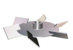
Turbine agitator
The ratio of the outer diameter, width, and height of the blade is generally 20:5:4, and the circumferential velocity is generally 3-8m/s. Turbine generates highly turbulent radial flow during rotation, suitable for the dispersion of gases and immiscible liquids, as well as liquid-liquid phase reaction processes. The viscosity of the stirred liquid generally does not exceed 25 Pa · s.
③ Paddle mixer
There are two types: flat propeller and inclined propeller. The flat blade agitator consists of two straight blades. The ratio of blade diameter to height is 4-10, and the circumferential velocity is 1.5-3m/s. The resulting radial fluid
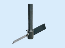
Inclined paddle mixer
The flow velocity is relatively low. The two blades of the inclined blade agitator (Figure 4) are folded at opposite angles of 45 ° or 60 °, resulting in axial liquid flow. The paddle agitator has a simple structure and is commonly used for mixing low viscosity liquids and dissolving and suspending solid particles.
④ Anchor mixer
The shape of the outer edge of the blade should be consistent with the inner wall of the mixing tank (Figure 5), with only a small gap between them, which can remove viscous reaction products attached to the tank wall or solid matter accumulated at the bottom of the tank, and maintain good heat transfer effect. The circumferential velocity of the blade edge is 0.5-1.5m/s, which can be used to stir Newtonian fluids with viscosity up to 200Pa · s
Anchor mixer
Compared to quasi plastic fluids (see viscous fluid flow), there is a significant stagnation zone in the liquid layer when stirring high viscosity liquids.
⑤ Spiral belt mixer
The outer diameter of the ribbon is equal to the pitch, and it is specifically used for stirring high viscosity liquids (200-500 Pa · s) and quasi plastic fluids, usually operated in laminar flow.
⑥ Magnetic stirrer
The Corning digital heater comes with a closed loop knob to monitor and adjust the mixing speed. The microprocessor automatically adjusts the motor power to adapt to water quality, viscous solutions, and semi-solid solutions.
⑦ Magnetic heating stirrer
The Corning digital heating mixer comes with an optional external temperature controller (Cat. No. 6795PR), which can also monitor and control the temperature inside the container.
⑧ Foldable agitator
Choosing the appropriate stirrer based on the physical properties, capacity, and stirring purpose of different media can play a significant role in promoting chemical reaction rates and improving production efficiency. The folding blade turbine agitator is generally suitable for reactions involving gas and liquid phase mixing, and the agitator speed should generally be selected to be above 300r/min.
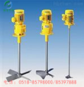
⑨ Variable frequency double-layer mixer
The base, support rod, and motor of the variable frequency mixer are fixed together using technology. Clamp head, no looseness, no swinging, will not fall off, safe and reliable. Chrome plated support rod, thick at the bottom and thin at the top, strong rigidity, and reasonable structure. It has the advantages of easy mobility and light weight. Suitable for various small containers.
⑩ Side entry mixer
Side entry mixer is a type of mixer that installs the mixing device on the side wall of the equipment cylinder. The mixer on the mixer usually adopts an axial flow type, with push type mixers being more common. Under the same power consumption, it can achieve good mixing effect, with power consumption only 1/3 to 2/3 of top mixing and cost only 1/4 to 1/3 of top mixing. The speed can be between 200-750r/min.
Widely used for desulfurization, denitrification, and agitation of various large storage tanks or tanks. Especially in large storage tanks or tanks, using one or more side entry mixers to work together can achieve good mixing results with low energy consumption.
agitation power
The power output P of the mixer to the liquid is calculated according to the following formula:
P=Kd5N3ρ
In the formula, K is the power reference number, which is a function of the stirring Reynolds number Rej (Rej=d2N ρ/μ); D and N are the diameter and speed of the agitator, respectively; ρ and μ are the density and viscosity of the mixed liquid, respectively. For agitators and mixing tanks with a certain geometric structure, the functional relationship between K and Rej can be experimentally determined and plotted as a curve, known as the power curve (Figure 7).
Basic calculation method for mixing power
In theory, although the mixing power can be divided into two aspects: mixer power and mixing operation power, in practice, only or mainly the mixer power is considered. As it is difficult to accurately measure the mixing operation power, the required mixing operation power is generally achieved by setting the speed of the mixer. Starting from the concept of agitator power, the main factors affecting agitator power are as follows.
① The structure and operating parameters of the agitator, such as the type of agitator, blade diameter and width, blade inclination angle, number of blades, agitator speed, etc.
② The structural parameters of the mixing tank, such as the inner diameter and height of the mixing tank, the presence or absence of baffles or guide vanes, the width and quantity of baffles, and the diameter of the guide vanes.
③ The physical properties of the stirring medium, such as the density of each medium, the viscosity of the liquid phase medium, the size of solid particles, and the gas medium permeability.
From the above analysis, it can be seen that the factors affecting stirring power are very complex, and it is generally difficult to directly obtain the calculation equation of stirring power through theoretical analysis methods. Therefore, using experimental methods combined with theoretical analysis is the only way to obtain the formula for calculating stirring power.
By using the Navier Stokes equations in fluid mechanics and representing them in dimensionless form, the dimensionless relationship equations (11-14) can be obtained.
Np=P/ρN³;dj5=f(Re,Fr)
Np in the formula - power reference number
Fr - Froude number, Fr=N²; dj/g;
P - stirring power, W。
In equations (11-14), the Reynolds number reflects the ratio of fluid inertial force to viscous force, while the Froude number reflects the ratio of fluid inertial force to gravity. Experiments have shown that, except in the transition flow state where Re>300, the Fr number has no effect on the stirring power. Even in the transition flow state where Re>300, the Fr number has little effect on most of the stirring blades. Therefore, in engineering, the power factor is directly expressed as a function of Reynolds number, without considering the influence of Froude number.
Due to the fact that the Reynolds number only includes the speed of the agitator, the diameter of the blades, the density and viscosity of the fluid, many other factors mentioned above must be set in the experiment, and then the relationship between the power standard and the Reynolds number must be measured. From this, it can be seen that all the relationship curves or equations between power parameters and Reynolds numbers obtained from experiments can only be used within a certain range of conditions. It is obvious that the relationship curve between power accuracy and Reynolds number varies for different blade types, and their Np Re relationship curves will also be different.
Mark an example of a slurry mixer with a diameter of 600mm and a shaft diameter of 40mm, labeled as mixer 600-40, HG5--220--65--5
Selection: Analysis and Introduction of Mixing Selection Steps
The design and selection of mixing devices are closely integrated with the purpose of mixing operations. Various mixing processes require the operation of different mixing devices. When designing and selecting, the mixer type, motor power, and mixing speed should be determined based on the purpose and requirements of the mixing operation according to the process. Then, various components such as reducer, frame, mixing shaft, and shaft seal should be selected. The specific steps and methods are as follows:
1. According to the process conditions, mixing purposes, and requirements, select the type of mixer. When selecting the type of mixer, it is necessary to fully understand the dynamic characteristics of the mixer and the causal relationship between the flow state generated by the mixer during the mixing process and various mixing purposes.
2. Based on the determined type of mixer and the flow state generated by the mixer during the mixing process, the control requirements of the process for mixing time, settling speed, and dispersion are determined through experimental methods and computer simulation design to determine the motor power, mixing speed, and mixer diameter.
3. Select the reducer model from the reducer selection table based on the motor power, mixing speed, and process conditions. If the gearbox is selected based on the actual working torque, the actual working torque should be less than the allowable torque of the gearbox.
4. Select frames and couplings of the same model and specifications according to the output shaft head of the reducer and the support method of the mixing shaft system
5. Select the shaft seal type according to the size of the mixing shaft head of the rack, installation capacity, working pressure, and working temperature
6. According to the installation form and structural requirements, design and select the mixing shaft structure type, and check its strength and stiffness.
If designed according to a rigid axis, n/nk ≤ 0.7 under strength conditions
If designed according to a flexible axis, n/nk>=1.3 under strength conditions
7. Choose to install the bottom cover, flange base or flange flange according to the nominal diameter DN of the rack, the type of shaft support and pressure rating of the mixing shaft
8. Determine whether to configure auxiliary supports based on the supporting and anti vibration conditions.
In the above selection process, the combination and configuration of the mixing device can refer to the schematic diagram of the mixing device design selection process. The key dimension for connecting various components during the configuration process is the shaft head size. Components with consistent shaft head size are generally interchangeable and combined.
Welcome customers to visit our company for product inspection and business negotiation. We will warmly welcome them!
Sales and Regional Hotline:
Service Department 1: 0518-85798000
Service Department 2: 0518-85397888
Manager Tang: 17768585576 18014441222
Email: jiangsubeijia@126.com