


I. Overview and Working Principle
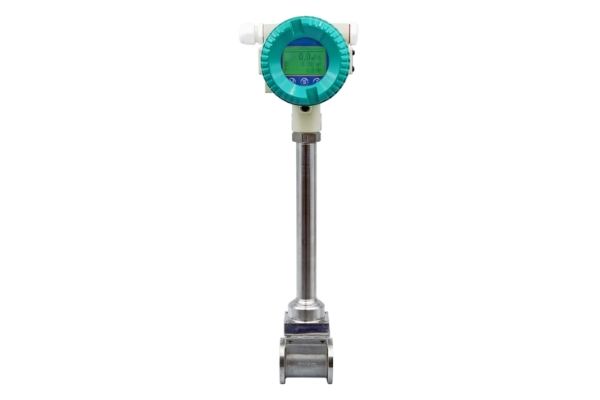
The AOLU series of intelligent full-tube vortex flowmeters is a new generation of flowmeters independently developed by our company. This instrument utilizes advanced microcomputer technology and new low-power consumption technology, featuring strong functionality, compact structure, simple operation, and convenient use.
This product is a new type of stress-type vortex shedding flow transmitter. The sensor outputs a voltage pulse frequency signal, which is easy to connect with a computer and can produce a 4-20mA standard signal.
Widely applicable in the oil, chemical, metallurgical, electric power, pharmaceutical, textile, and water supply industries, as well as for the measurement and control of water and gas pipelines at natural gas stations.
The vortex flow sensor/transmitter is mounted on the pipeline, while the flow totalizer or computer is installed in the control room and provides power to the vortex flow sensor/transmitter. They are connected using shielded cables.
The circuit section of the split-body vortex shedding flowmeter is separated from the meter body. The circuit section is installed in a location with good environment and easy detection, and it is connected to the meter body with a dedicated cable ≤10m long at the factory.
Section II: Structure and Principle
This product is based on the Karman vortex street principle. When a non-streamlined probe (such as a triangular prism) is vertically inserted into the liquid in a pipe, and the flow rate is sufficiently high, alternating vortices are produced downstream of the flow element. As the vortices grow larger, they move away from the downstream of the flow element, forming two rows of vortices, known as a vortex street (as shown in the right figure). This process is called vortex shedding. The frequency of vortex shedding is related to the fluid flow velocity and the width of the cylindrical body, and is linearly related to the fluid velocity within a certain flow rate range, and this relationship is not affected by the fluid's density, viscosity, pressure, or temperature. Due to the pressure pulsations generated on both sides of the cylinder during vortex shedding, the probe body experiences alternating stresses, causing piezoelectric crystal elements embedded within the probe body to produce alternating charges under the alternating stress. The detection amplifier transforms these alternating charges and outputs a pulse signal proportional to the fluid velocity, which is then sent to a totalizer (or the calculation unit of an intelligent meter) for processing, display, or output as a 4-20mA standard current signal.
III. Features
1. Good versatility of medium, capable of measuring liquids and gases
Liquids: Water, softened water, gasoline, kerosene, diesel, liquefied petroleum gas, liquid ammonia, phosgene, alkanes, alkenes, alcohols, aldehydes, and various other chemical liquids
Gases: Air, Oxygen, Nitrogen, Natural Gas, Liquefied Gas, Ammonia, Chlorine, Alkanes, Alkenes, Hydrocarbons, and various other gases
No moving parts, simple structure, high reliability.
2. The main body and vortex generator are constructed with high-quality stainless steel, ensuring a long service life.
3. The flow parameters of the instrument are unaffected by measurement parameters such as pressure, temperature, density, viscosity, and composition.
4. High instrument accuracy and repeatability; wide measurement range, up to 1:15 or more.
5. Low instrument pressure loss, low operating costs, and significant energy-saving implications.
6. The output signal is linearly related to the flow, featuring pulse signals, analog signals, etc.
7. Employing a new type of piezoelectric crystal signal processing amplifier and unique filtering technology, effectively eliminates interference signals caused by pressure fluctuations and pipeline vibrations, significantly enhancing the flowmeter's anti-interference capability.
外形结构与安装尺寸
Dimensions for Appearance Installation
Installation Dimensions (Unit: mm)
Nominal Bore Size | Body Internal Diameter (D) | Outside Diameter (D1) | Table Length (L) | Height (H) |
15 | 15 | 39 | 65 | 300 |
20 | 20 | 50 | 65 | 300 |
25 | 25 | 57 | 65 | 300 |
32 | 32 | 65 | 65 | 305 |
40 | 40 | 75 | 65 | 305 |
50 | 50 | 87 | 65 | 310 |
65 | 65 | 109 | 65 | 315 |
80 | 80 | 120 | 65 | 315 |
100 | 100 | 149 | 65 | 325 |
125 | 125 | 175 | 85 | 335 |
150 | 150 | 203 | 85 | 350 |
200 | 200 | 259 | 105 | 375 |