


Product Application Scope
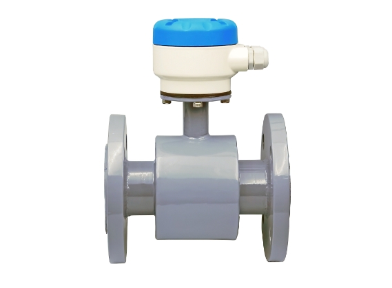
The electromagnetic flow meter consists of two parts: a sensor and a converter. It operates based on Faraday's law of electromagnetic induction and is used to measure conductive liquids or two-phase media. The electrical conductivity of the medium should generally be greater than 5μS/cm (the electrical conductivity of tap water is approximately 100-500μS/cm). It can be used to measure various media such as acid, alkali, salt solutions, pulp, slurry, etc., but the medium should not contain excessive ferromagnetic materials and a large number of bubbles.
A magnetic flow meter is a primaryFlowmeterWidely used in flow measurement for various industrial sectors including oil, chemicals, metallurgy, light industry, papermaking, environmental protection, food, as well as municipal management and hydraulic construction.
Section 2: Working Principle
The measurement system of an electromagnetic flow meter sensor is based on Faraday's Law of electromagnetic induction. A pair of detection electrodes is installed on the tube wall, perpendicular to the axis of the measuring tube and the magnetic field lines. When the conductive liquid moves along the axis of the measuring tube, it cuts through the magnetic field lines, generating an induced electromotive force (emf). This induced emf is detected by two electrodes on the measuring tube, with its magnitude being:
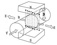
E=KBVD
E Induced Electromotive Force
K Instrument Constant
B Magnetic Induction Intensity
Measure the average flow velocity within the V cross-section of the pipe.
Inner diameter of the D measuring tube.
When measuring flow, the fluid passes through a magnetic field perpendicular to the flow direction. The flow of conductive liquids induces an electric potential proportional to the average flow velocity, thus requiring the measured liquid flow to have a conductivity above a minimum threshold. The induced voltage signal is detected through two electrodes and transmitted via cable to a converter. After signal processing and relevant calculations, the cumulative and instantaneous flow rates are displayed on the converter's screen.
Section 3: Instrument Features
1. The measuring tube is free of obstructions and moving parts, thus preventing additional energy loss and clogging. This results in significant energy-saving effects, making it particularly suitable for measuring two-phase flows such as wastewater, sludge, mineral slurry, coal-water slurry, and pulp.
2. Only the lining and electrodes come into contact with the medium being tested. By selecting the lining and electrode materials appropriately, excellent corrosion and wear resistance can be achieved, thus allowing for the measurement of various strong acids, alkalis, and other chemical solutions.
3. Low installation requirements. The front straight pipe section requires only 5D, while the rear straight pipe section is 2D (D being the internal diameter of the selected instrument).
4. The measurement accuracy is unaffected by changes in fluid density, viscosity, temperature, pressure, and conductivity, and can measure flow in both directions (positive/negative), providing an excellent means for accurate flow measurement.
5. The instrument has a low power consumption, less than 5VA.
6. The converter offers excellent interchangeability and can achieve measurement accuracy without the need for re-calibration of actual flow. Due to its series of advantages, the electromagnetic flow meter is gaining more widespread application across various industries and has become the preferred instrument for liquid flow measurement.
Section 4: Order Instructions
Please read this information thoroughly before placing an order to understand the model and coding specifications of this product and determine the required model and specifications.
Please fill out the electromagnetic flowmeter selection operating conditions table if necessary.
AO-ATF-A/B (Integral/Seperate) Universal Electromagnetic Flowmeter Technical Specifications
1. Size: DN10 to DN2000
2. Electrode Materials 316, Hb, Hc, Ti, Ta, Pt
3. Lining Material - PTFE, PFA, F46, Chlorinated Butyl Rubber, Polyurethane
4. Medium Conductive Liquid (including solid-liquid two-phase systems)
5. Measurement Error: ±0.3%, ±0.5%, ±1.0% Flow Rate (divided by diameter)
6. Medium Conductivity > 5μS/cm (water > 20μS/cm)
Flow Rate Range: 0.5~10 m/s (Flow Unit Selectable)
8. Flanged Connection GB9115 National Standard or as per customer's requirement
9. Medium Temperature - Integral type: -10℃ to +60℃; Segmented type: -10℃ to +150℃
10. Rated Pressure: 0.6MPa ~ 4.0MPa (divided by diameter)
11. Protection Rating: IP65, IP67, IP68 (Split Type)
12. Converter Design - Integrated, Split-Type
13. Output Signal 4-20mA Output, Frequency/Pulse Output
14. Communication: RS485, RS232
15. Applications: Acids, Alkalis, Water Supply and Drainage, Food, Pulp, Mineral Slurry, etc.
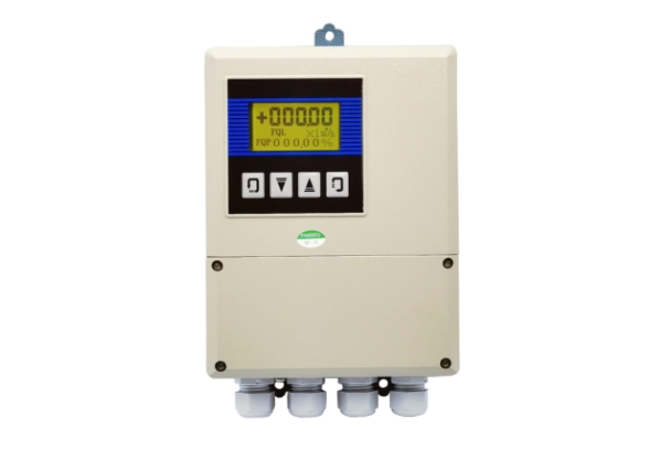
16. Display: Flow rate, flow volume, percentage, cumulative flow, fault alarm, etc.
17. Power Supply: 220VAC, 24VDC
18. Installation Type: Integrated or Split Type
AO-ATF-C/D (Integrated/Discrete) Clamp-on Electromagnetic Flow Meter Technical Specifications
1. Size: DN10 to DN200
2. Electrode Materials - 316, Hb, Hc, Ti, Ta, Pt
3. Lining Material PFA, F46
4. Medium Conductive liquid (including solid-liquid two-phase system)
5. Measurement Error: ±0.3%, ±0.5%, ±1.0%
6. Medium Conductivity >5 μS/cm (Water >20 μS/cm)
7. Flow Range: 0.5~10 m/s
8. Medium Temperature - Integral Type: -10℃ to +60℃; Segmented Type: -10℃ to +150℃
9. Rated Pressure: 1.6MPa ~ 4.0MPa (divided by diameter)
10. Protection Class IP65, IP67, IP68 (separated)
11. Output Signal 4-20mA Output, Frequency/Pulse Output
12. Communication: RS485, RS232
13. Applications: Acids, alkalis, water supply and drainage, food, pulp, etc.
14. Display: Flow Rate, Flow Volume, Percentage, Cumulative Flow, Fault Alarm, etc.
15. Power Supply: 220VAC, 24VDC
16. Installation Type: Integrated or Split Type
V. Technical Specifications of Smart Converter
Conductivity | >5μS/cm |
Flow Rate Range | 0.5~ 10m/s |
Current Output | Bi-directional two-way, fully isolated, 0-10mA (load resistance 0-1.2KΩ) 4-20mA (Load Resistance 0-600Ω) |
Frequency Output | The upper limit is set within 0~3KHz. Collector open circuit output with photoelectric isolation. |
Pulse Output | Maximum up to 5000cp/s, pulse energy ranging from 0.0001 to 10m3/cp. Pulse width is 10ms to 2.5s.报警output with optocoupler isolation, collector open circuit alarm output with optocoupler isolation, and collector open circuit output for both forward and reverse flow states. All three outputs have an external power supply not exceeding 35V, with a collector current of 250mA when conducting. |
Communication Interface | RS485,RS232 |
Isolation | Simulated output, pulse output, alarm output, and insulation voltage to ground not less than 500V |
Power Supply | 220VAC,24VDC |
Power | ≤20W |
Ambient Temperature | -10~+ 60℃ |
Display | High-resolution backlit LCD display, instantaneous, cumulative (positive cumulative, negative cumulative, and differential cumulative) |
Power Failure Protection | Data on cumulative values saved for more than 10 years |
Shell Protection | IP65, IP67, IP68 (split type) |