


AOUL65 Horn Antenna Radar
Emission Angle: 6°, 8°, 9°
Signal Strength: Strong, Medium, Weak
Miniature Flange: DN125, DN100, DN80
Moisture-sensitive, condensation water
Among various types of antennas, the signal strength is relatively strong.
Solid measurement range reduced by half
Dust measurement range reduced by two-thirds
As follows:
Test solid 5 meters, 5*2=10 meters
If the range is selected to be 30 meters, the factory standard is marked as 5 meters; if 7 meters is chosen, there might be on-site risks.
12-meter dust measurement, 12 x 3 = 36 meters
Select the model with a range of 70 meters.
26 GHz
Measurement Distance: 70,307 meters
Resolution: 1mm
Accuracy ±10mm
±5mm tolerance
0.6m Blind Spot
Measurement interval ≥ 1s, based on set parameters
Response time ≥ 5s, based on set parameters
Beam Angle < 8°
Dimensions (excluding flange): 120*94*320mm
Flange sizes: DN50, DN80, DN100, DN150
Process Temperature -40℃ to 85℃
Process pressure: Atmospheric pressure
Relative humidity < 95% RH
Antenna Material: PTFE
Power supply: 16~36VDC, two-wire or four-wire system (HART); 9~24VDC, four-wire system (RS485)
Signal Output HART/4-20mA/RS485
Fault output does not change/22mA/20.5mA/4mA
500Ω high load
Communication HART/RS485
Live Display LCD Panel
Ingress Protection (IP) 67
Cable entry M20x1.5
Recommend AWG 18 or 0.75mm² cable
External measurement suitable for complex process conditions of various containers, tanks, and materials storage, unaffected by changes in the physical properties of the medium being measured. Two-wire technology, suitable for explosion-proof environments, non-contact and continuous measurement pulse-type level gauge with a large measuring distance of up to 70 meters.
I. Features and Advantages:
Two-wire technology is an excellent substitute for differential pressure gauges, magnetostrictive sensors, radio frequency admittance, and magnetic flip-flop gauges.
Not affected by environmental factors such as pressure changes, vacuum, temperature variations, inert gases, dust, steam, etc.
Easy to install, sturdy and durable, maintenance-free
HART Communication Protocol and Foundation Fieldbus Protocol, with simple calibration and easy on-site calibration operations via digital LCD display, simple configuration settings and programming achieved through the software AOPF.
Highly sensitive in measurement, with rapid refresh speed.
Suited for high-temperature operating conditions, with process temperatures up to 200°C, and can reach 350°C when using high-temperature extended antennas.
Section 2: Application Medium:
The AOUL60 series radar level gauge is suitable for non-contact continuous measurement of liquid, slurry, and granular material levels, applicable to environments with significant temperature and pressure fluctuations, as well as those with inert gases and volatile substances.
Utilizes microwave pulse measurement methods and operates normally within the industrial frequency band. The beam energy is low, allowing for installation in various metal and non-metal containers or pipes without harm to humans or the environment.
III. Measurement Principle
Low-power short microwave pulses are emitted and received through an antenna system. Radar waves travel at the speed of light. Operating time can be converted into level signals by electronic components. A special time extension method ensures stable and effective measurements in a short period.
Even in complex operating conditions where false echoes are present, the new microprocessing technology and debugging software can accurately analyze the echo of the material level.
Input
The antenna receives reflected microwave pulses and transmits them to the electronic circuit. The microprocessor processes this signal, identifying the echoes generated by microwave pulses on the material surface. Accurate echo signal identification is performed by intelligent software, achieving precision down to the millimeter level. The distance D from the material surface is proportional to the pulse's travel time T:
D=C×T/2
Where C is the speed of light.
Since the distance E to the empty cans is known, the level L is:
L=E-D
Output
Set by entering the empty tank height E (= zero point), full tank height F (= full scale), and some application parameters. The application parameters will automatically adjust the instrument to the measurement environment. Corresponds to a 4-20mA output.
Radar level gauge output calculation:
At the factory, the default mode is height measurement.
50-meter range, 0.6-meter blind spot
Then, there are:
At material level 0, the indicator shows: 50 meters, output 4 mA
At 49.4 meters, gauge shows: 0.6 meters, output 20 mA
Milliamp output calculation formula:
Ex Works Default
Milliamp Output = 20 - (Display Value - Dead Zone) / (Range - Dead Zone) * 16
Header Display = Range - Material Height
30-meter range, 0.6-meter blind spot
Then, there are:
At material level 10, the gauge displays: 20 meters.
Output: 9.442 mA
30-10=20
20-(20-0.6)/(30-0.6) *16=9.442
At 20 meters, the gauge reads: 10 meters.
Output: 14.884 mA
30-20=10
20-(10-0.6)/(30-0.6) *16=14.884
30-meter range, 0.6-meter blind spot
How do I set up the DCS or instrument to display it?
4mA corresponds to 0mm material height
20 milliamperes corresponds to the material height of (range - dead zone)
30 - 0.6 = 29.6 meters
Distance display is referenced to the installed benchmark point.
Milliampere output is referenced to the blind area.
This is where the radar differs from other products and has become a customary practice.
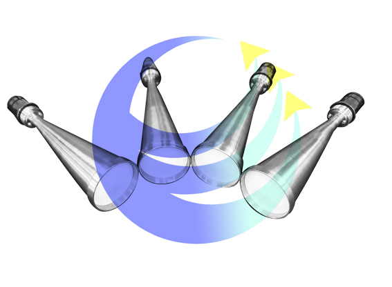
Above image shows an antenna with a protective hood.
Select dustproof antenna
Greatly enhance dust-proof performance
Increase dustproof horn antenna
Signal will weaken
Compared to standard horn antennas
The range must be reduced by 25%.
Of course, in addition to dustproof antennas.
Resolve dust issues by choosing models with a blowing device.
In-situ, the blow-off method is preferred if it can be conditionally utilized, as this method does not weaken the signal.