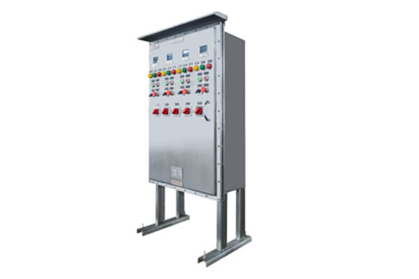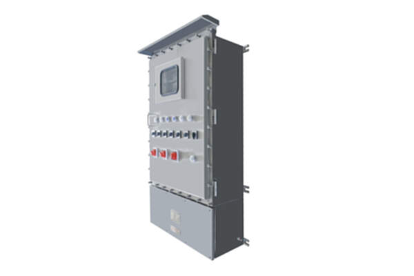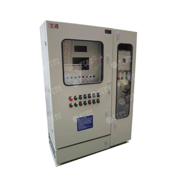

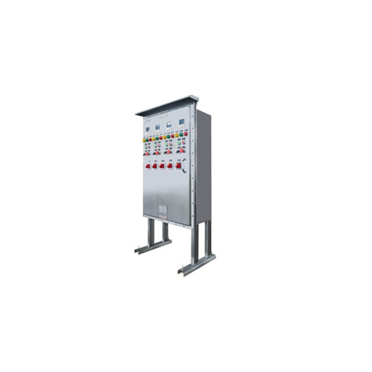








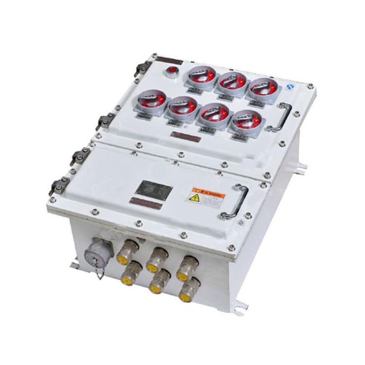


Product Structure Overview of 316 Stainless Steel Explosion-Proof Pressure Cabinet
This product is suitable for factories in various industries such as petrochemicals, offshore drilling platforms, metallurgy, light industry, textiles, food, biotechnology, aerospace engineering, and hazardous chemical storage facilities, where there are Class II A, II B, II C T1 to T4 explosive gas or vapor environments; altitudes not exceeding 2,000 meters; relative humidity below 95% at 25°C; and operating temperatures between -20°C and +40°C.
Various standard detection, analytical, display instruments, microcomputer touchscreens, and electrical components can be installed according to customer requirements, with minimal restrictions on the internal electrical components of the customer's unit.
The distribution cabinet is composed of the cabinet body, automatic control system, gas distribution system, alarm system, and power distribution system; the cabinet body features an upright structure with an upper positive pressure chamber and a lower auxiliary chamber. The auxiliary chamber houses the automatic control system, alarm system, and the user's incoming and outgoing cables; the positive pressure chamber contains explosion-proof components of the automatic control system and the user's power distribution system components.
The distribution cabinet features a ventilation-type air intake, providing continuous, uninterrupted airflow. The working heat of the components inside the positive pressure chamber can be carried away through the air circuit, offering excellent heat dissipation.
This product is designed, manufactured, and inspected in accordance with GB3836.1-2000, GB3836.5-2004, and related standards.
The operating principle of the 316 stainless steel explosion-proof pressure cabinet
The distribution cabinet, under the control of the automatic control system, introduces protective gas. The pressure inside the positive pressure chamber is higher than that outside, creating a micro-positive pressure safe environment. This prevents flammable hazardous gases from entering the positive pressure chamber, ensuring the safe operation of ordinary instruments and electrical components inside.
The automatic control system primarily handles a series of functions including automatic air exchange, air replenishment, high-pressure alarm (or exhaust), low-pressure alarm, low-pressure interlock, and air exchange interlock.
The distribution box meets the customer's requirement with a low-pressure interlock function, automatically cutting off the user's power supply to the positive pressure chamber when the pressure value falls below the specified limit (50Pa).
Installation of 316 Stainless Steel Explosion-Proof Pressure Cabinet
One. Cabinet Installation
1. Cabinet installation location: Indoor or outdoor with a roof, on a flat surface with no noticeable vibration.
2. This product is designed for floor-standing installation. There are dedicated mounting holes provided at the bottom of the product. Specific parameters are detailed in the technical drawings.
3. The wiring method is cable trench wiring. The user can refer to relevant national and industry standards for the cable trench structure and design and construct it in accordance with the structural requirements of this cabinet.
4. Caution during handling: This product must not be tilted excessively; the tilt angle should not exceed 10 degrees.
5. It is strictly prohibited to use prying or hammering methods for handling this product during transportation and installation. Otherwise, it may affect the product's sealing performance, leading to the failure of the product to operate normally.
6. This product is equipped with an intake and exhaust port. The exhaust port can be discharged on-site or directed to a safe area. On-site discharge requires passing through a fire damper before release. Users must provide an intake gas source (clean gas) on-site, with the gas pressure generally controlled between 0.2-0.8 MPa. When the intake gas source is nitrogen (note: nitrogen should be used cautiously as a protective gas in enclosed operation rooms. If nitrogen must be used as a protective gas, ensure proper ventilation on-site to ensure personal safety).
7. Due to the presence of precision electrical components such as industrial control electronics and touchscreens, a desiccant filter must be installed at the air source inlet to ensure the air is dry and clean. Otherwise, it may affect the lifespan of the electrical appliances.
8. Absolutely no adjustment of the pressure-reducing valve is permitted; otherwise, it may cause a high-pressure surge to the cabinet (the pressure-reducing valve has been adjusted at the factory).
Section 2: Installation of Customer Components
1. As the internal power system components are adjusted by the user, installations, settings, and adjustments must be performed within the safety zone.
Do not disassemble electrical components from the panel to avoid affecting the cabinet's airtight performance.
III. Electrical Installation
1. This product must be operated by a professional electrician.
2. Users shall follow the technical documents provided by our company, including electrical system diagrams, wiring diagrams, terminal tables, etc., and match the wiring one by one according to the actual product conditions.
3. During wiring, please ensure the sealing integrity of all incoming and outgoing cables (never discard the sealing rings in the connectors), and, based on the tension of each cable, apply appropriate sealing with explosion-proof putty.
4. After users complete the wiring and debugging, ensure that all doors are sealed properly when closing them.
5. This cabinet must connect the ground wire to the designated grounding screws as required.
Five: Product Tuning
One, this product is suitable for AC220V, 50Hz power distribution systems.
Part Two: The product adjustment is divided into two parts.
1. Self-control section tuning
Pre-check before tuning
The self-control system primarily consists of explosion-proof electrical equipment of the explosion-proof type, mainly comprising explosion-proof casings, intermediate relays, time relays, and pressure gauges. Inspect each part for any damage or defects, check the explosion-proof performance, ensure correct wiring, and verify that the manual valve is open. Proceed with debugging only when everything is normal.
2) Debugging Method
A. Upon closing the door for debugging, after configuring the gas source, the inlet manual valve must be fully open. Connect the power supply, turn the knob to the "Start" position. The red "Power Indicator" light will illuminate. At this point, the inlet solenoid valve and the exhaust solenoid valve are fully open, and the timer begins. The self-control system enters the ventilation stage, and the yellow "Ventilation Indicator" light turns on.
B. After 10 minutes, the yellow "Venting Indicator" light extinguishes, and the green "Automatic Indicator" lights up, indicating the end of venting. At this point, all intake and exhaust valves are closed, and the sensor system performs pressure detection. If the pressure in the positive pressure chamber exceeds 50Pa, power is supplied to the main cabinet's power distribution system via the contactor; otherwise, power supply is not possible. The cabinet then enters a normal pressure maintenance state. During this process, the internal pressure can be adjusted using the bypass precision pressure regulating valve to maintain a steady level around 300Pa. At this stage, the entire cabinet startup process is complete.
During operation, if the internal pressure of the cabinet drops below 100Pa due to an external gas source, the "low-pressure alarm" bell will ring, and the inlet solenoid valve will open to replenish the positive pressure chamber. When the pressure is replenished to 1000Pa, the inlet solenoid valve will close, entering the pressure maintenance phase. At this point, it is necessary to identify and eliminate the cause of the pressure drop in the positive pressure chamber from the external gas source. Otherwise, the internal pressure of the positive pressure chamber will fluctuate frequently, causing the solenoid valve to operate frequently, leading to unstable operation of the entire cabinet. Therefore, it is essential to stabilize the system by adjusting the bypass precision pressure regulating valve, ensuring that the relative pressure within the system is maintained around 300Pa. This will determine the stability of the automatic control system and the entire cabinet operation.
D. In the event that the positive pressure value inside the inverted positive pressure chamber drops below 50Pa due to external gas source reasons, the automatic control system will disconnect the power supply to the user's system, entering the "under-voltage protection" phase. The automatic control system will only automatically restore normal power supply to the main circuit once the pressure in the positive pressure chamber rises above 50Pa.
3) Debugging Precautions:
This product is factory-set upon shipment; users are strictly prohibited from altering the parameters. Please ensure that the gauges, automatic control lines, and sampling pipelines are clear during the adjustment process.
2. Partial debugging of the user's power distribution system
1) After transportation and installation, this product must be strictly inspected and adjusted in accordance with the standards for low-voltage complete sets of equipment.
2) Refer to the technical accessories (assembly drawings, etc.) included with this product and compare them with the customer's design drawings one by one for inspection and operation.
3) Upon opening for debugging, only tune the power distribution system.
Upon completion of the adjustment, the product is ready for delivery.
Section 6: Product Maintenance
One, regularly inspect the aging of the seals, and replace them immediately upon discovery of aging.
The explosion-proof distribution box's blast-proof joint surfaces must be treated for rust resistance. Each time the box is inspected or the cover is opened, the 204-1 rust-inhibiting oil must be reapplied.
3. Each time panel components are replaced, their sealing should be checked.
Seven precautions
1. Due to the possibility of containing adjustable components such as touch screens and PLCs in this container, please install the corresponding programs within the safety zone. Absolutely forbidden to open the cover and operate with power in the explosion-proof zone!!
2. To enable users to correctly select, install, and operate this equipment, this "Manual" is specially prepared for your reference. This "Manual" provides a detailed introduction to the structure, working principle, installation, debugging, operation, and maintenance of the product, tailored to the actual conditions of our company's product.
3. Prior to installation and use, users must carefully read this "Manual" and strictly follow the instructions provided. Otherwise, any quality issues arising from failure to do so will not be the responsibility of our company.