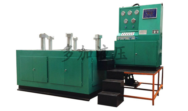


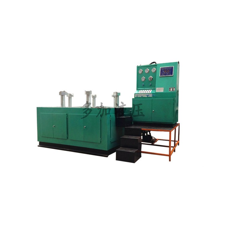


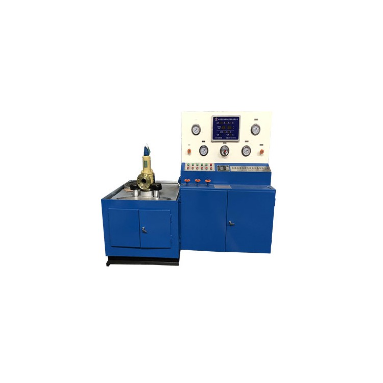
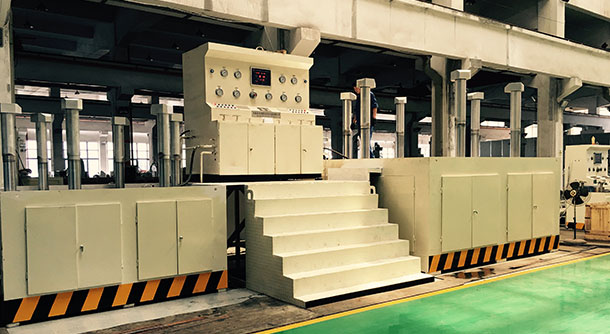
The DYFJ-H2400 valve testing bench is the fourth generation pressure testing and detection equipment independently developed by Duojia Hydraulics, based on years of production experience and in compliance with national standards and specifications.
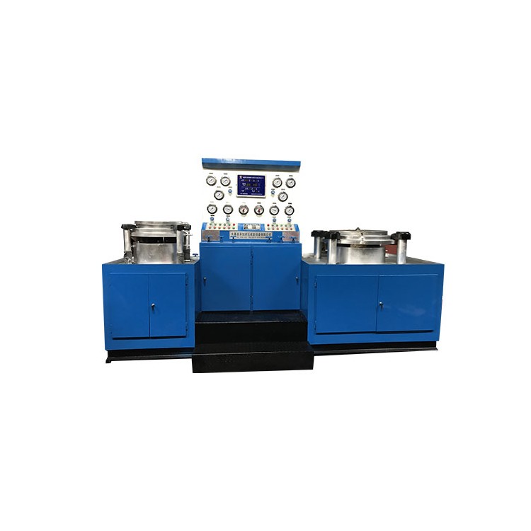
The DYFJ-H2400 type valve test bench integrates mechanical and electrical, hydraulic systems, pressure testing, and the storage and recycling of liquid mediums. It features comprehensive functions, stable performance, and high degree of automation. It is widely used for sealing face leakage testing of various high, medium, and low-pressure valves with nominal diameters of 1200-2000mm, as well as for shell strength (pinhole) and other performance tests. Test mediums: water, gas, oil.
The equipment is hydraulically driven and electrically controlled throughout the entire process, exerting no additional external force on valves that could affect test results. This significantly enhances work efficiency and reduces labor intensity, making it an ideal new generation pressure testing and inspection equipment for valve manufacturing companies, users, and maintenance units.
DYFJ-H2400 type valve testing bench working principle and structure
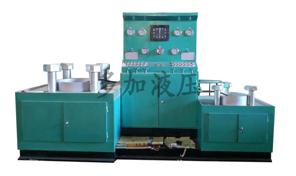
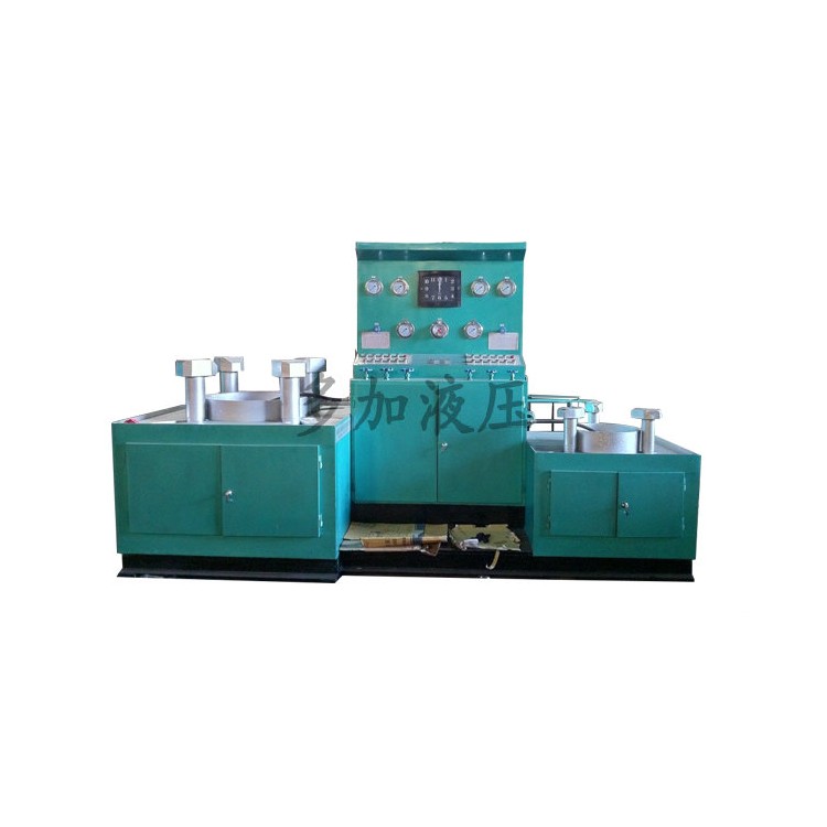
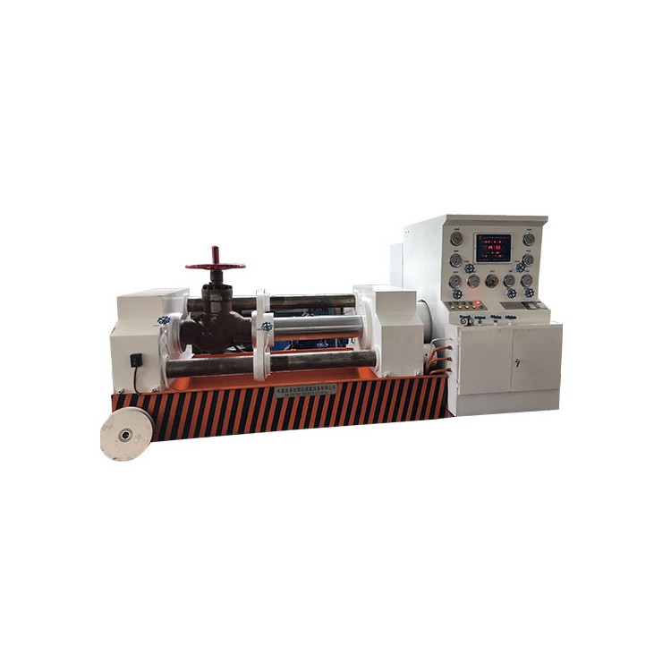
The DYFJ-H2400 type valve test bench operates by positioning the valve flange and clamping the back of the flange with movable claws, ensuring that no external force that could affect test results is applied during valve testing, meeting national standard requirements for valve testing.
Equipment is broadly categorized into hydraulic pressure supply systems, electrical control systems, water circulation systems, and various operating devices.
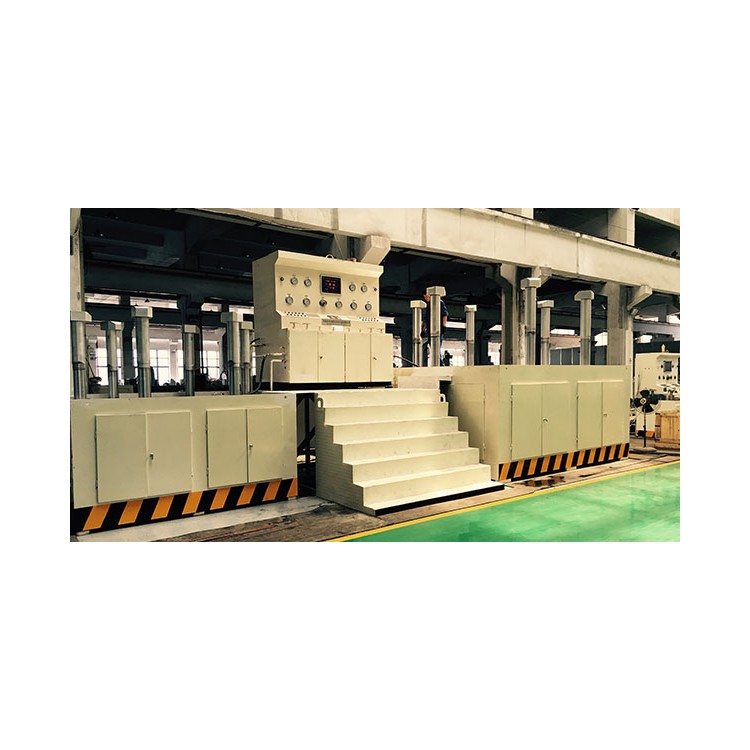
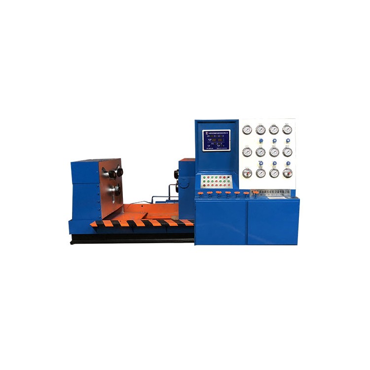
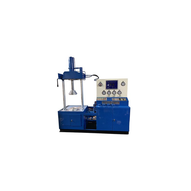
The equipment features a clamp-type design, with each side of the workbench sealed with a blind plate. The hydraulic clamp has both axial extension and radial movement capabilities, directly driven by a hydraulic cylinder to ensure uniform force distribution on the valve sealing surface for reliable clamping. During butterfly valve testing, the valve's sealing performance can be directly observed, facilitating the inspection of gas tightness tests and the observation of the valve sealing surface. It boasts excellent performance and a simple, compact structure.
Technical Specifications
| Model | DYFJ-H300 | DYFJ-H600 | DYFJ-H800 | DYFJ-H1200 | DYFJ-H1600 | DYFJ- | DYFJ- | DYFJ- | |
Valve Test Passages Allowed | DN50-300 | DN50-300 | DN50-350 | DN300-600 | DN350-800 | DN1200- | DN1200- | DN1400- | |
DN300-600 | DN400-800 | DN700-1200 | DN900-1600 | ||||||
Power Supply | Voltage V | 380 | 380 | 380 | 380 | 380 | 380 | 380 | 380 |
Frequency Hz | 50 | 50 | 50 | 50 | 50 | 50 | 50 | 50 | |
Motor | Power kW | 2.2 | 3 | 3 | 5.5 | 5.5 | 7.5 | 7.5 | 7.5 |
Grade P | 6 | 6 | 6 | 6 | 6 | 6 | 6 | 6 | |
System Pressure Regulation Range | 0-6.3 | 0-6.3 | 0-6.3 | 0-6.3 | 0-6.3 | 0-6.3 | 0-6.3 | 0-6.3 | |
Hydraulic CylinderToHigh working pressure | 31.5 | 31.5 | 31.5 | 31.5 | 31.5 | 31.5 | 31.5 | 31.5 | |
ToLarge Valve Flange | 520 | 845 | 1085 | 1485 | 1930 | 2345 | 2475 | 2760 | |
To small valve flange | 165 | 440 | 520 | 860 | 1075 | 1405 | 1630 | 1830 | |
Press claw onto the working diskPlease provide the Chinese content you would like translated into American English.Long distance | 370 | 370,620 | 370,637 | 620,1225 | 637,1225 | 1225 | 1250 | 1250 | |
PumpPlease provide the Chinese content to be translated.High Pressure (MPa) | 10 | 10 | 10 | 10 | 10 | 10 | 10 | 10 | |
Overall dimensions | L (mm) | 2000 | 3500 | 3600 | 4900 | 5200 | 4500 | 5000 | 5500 |
B (mm) | 1200 | 1350 | 1500 | 2200 | 2350 | 2750 | 3300 | 3600 | |
H (am) | 1850 | 1980 | 2050 | 2050 | 2200 | 2200 | 2200 | 2200 | |
Weight (kg) | 2000 | 4500 | 6000 | 8000 | 9800 | 9000 | 11500 | 13000 | |
DYFJ-H2400 Type Top-Clamping Oil Cylinder Pressure Comparison Chart DYFJ-H2400 type clamping cylinder pressure contrast table | |||||||||||||||
Nominal Bore Size NominalDiameter | |||||||||||||||
| 0.6MPa | 1.0MPa | 1.6MPa | 2.0MPa | 2.5MPa | 4.0MPa | 6.4MPa | |||||||||
| 150 | 400 | ||||||||||||||
Hydraulic System Pressure (Boost) MPa Hydraulic system pressure(pressure increasing) | |||||||||||||||
| in | mm | PN | PS | PN | PS | PN | PS | PN | PS | PN | PS | PN | PS | PN | PS |
| 64″ | DN1600 | ● | ● | ● | ● | ● | ● | ||||||||
| 72″ | DN1800 | ● | ● | ● | ● | ||||||||||
| 80″ | DN2000 | ● | ● | ● | ● | ||||||||||
| 88″ | DN2200 | ● | ● | ||||||||||||
| 96″ | DN2400 | ● | ● | ||||||||||||
Operation Instructions
1. Valve Mounting Method
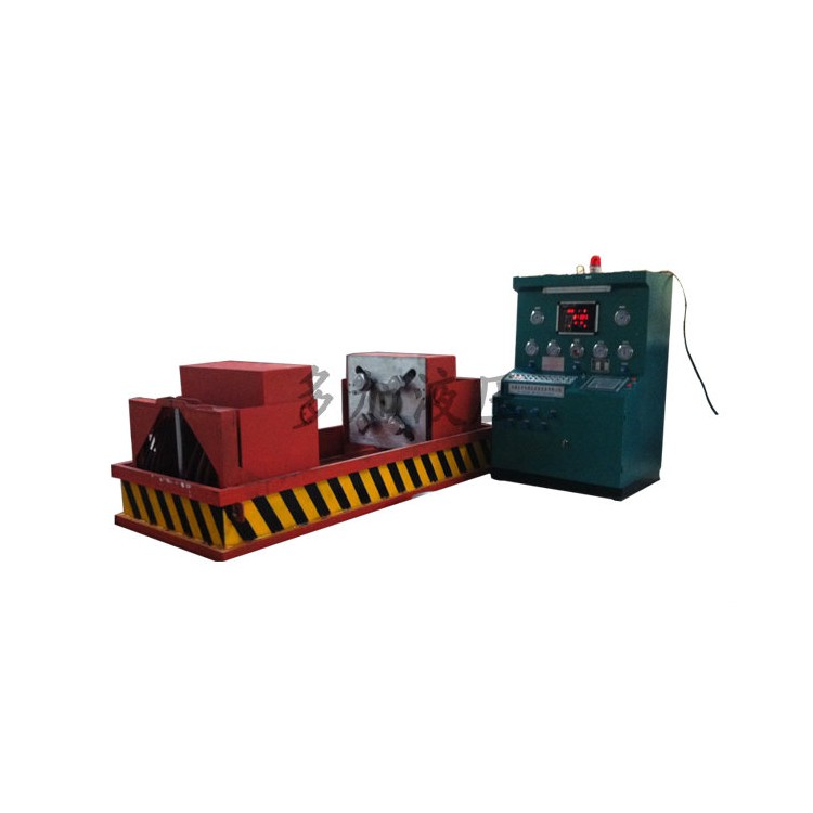
Select a valve with a nominal bore diameter corresponding to the equipment model, turn on the power, and start the hydraulic system. Move the hydraulic clamping jaw radially to exceed the outer diameter of the test valve flange, and extend the axial movement of the clamping jaw to exceed the valve length. Place the lower flange of the valve face-to-face against the workbench blind plate, aligning with the center opening. Move the radial clamping jaw close to the valve flange, and move the axial clamping jaw to ensure the clamping jaw is tightly against the front of the valve flange. At this point, the valve is securely held in place by the clamping system, ensuring the valve does not wobble.
During the strength test of the valve body, the other end of the valve to be tested is tightly sealed against the upper pressure test blind plate, aligned with the center opening. Radially move the clamping jaws close to the valve flange. Axially move the clamping jaws to make the jaws tightly abut the back of the valve test blind plate. At this moment, the valve should be securely held and fixed by the clamping system, with the valve in a stable overall state.
2. Water Pressure Testing Method (Double-direction Inflow and Drainage)
After the valve clamp is installed, refer to the "Clamping Cylinder Pressure Comparison Table" to increase the hydraulic clamp's gripping force to the required pressure. Adjust the electrical contact pressure gauge (for example, for a 25 kg valve, adjust the gauge pointer to 2.5 MPa). Open the main water inlets, left and right water inlets, close the air inlet, drain, and vent valves. Start the low-pressure water pump, observe the movement of the pressure gauge pointer. When the pointer stops rising, it indicates that the valve cavity is filled with water. Start the high-pressure water pump; the pump will automatically stop when the water pressure reaches the pressure set on the electrical contact pressure gauge. The equipment then enters the pressure maintenance state.
Upon reaching the pressure-holding time, the valve is problem-free. First, open the water drain valve to release the water pressure inside the valve chamber, then remove the valve.
3. Pressure Testing Methods (Bi-directional Intake, Exhaust)
The equipment does not come with a gas source. The user must provide a separate gas source. Please consult the manufacturer before using high-pressure gases.
After the valve mounting is complete (using pressure air as an example, generally not exceeding 10 kg of pressure), open the water and air intake valves, and close the water and air release valves. Close the water and air intake valves when the pressure gauge reaches the maximum pressure, and the equipment remains in a pressure-holding state.
Upon reaching the pressure-holding time, the valve shows no issues. First, open the vent valve to release the pressure inside the valve chamber, then remove the valve.
Instructions and Requirements for Use
Ensure the equipment is level during installation or secure the base channel steel with concrete.
2. Use 46-grade anti-wear hydraulic oil (select antifreeze 46-grade anti-wear hydraulic oil below 0℃), ensuring the oil level does not fall below the indicator. Regularly check the oil level and hydraulic oil. After one year of use, clean the oil tank and replace the hydraulic oil.
3. Add rust inhibitor to the recirculating water; replace the water promptly once the water quality degrades.
4. The equipment work surface should be kept clean, and there should be no debris between the valve flange under test and the pressure testing blank flange.
5. All moving parts of the test bench should be lubricated and kept clean for smooth operation.
6. Operators must undergo professional training before starting work, adhere to standard procedures, and prioritize safety.