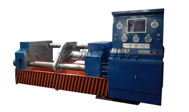


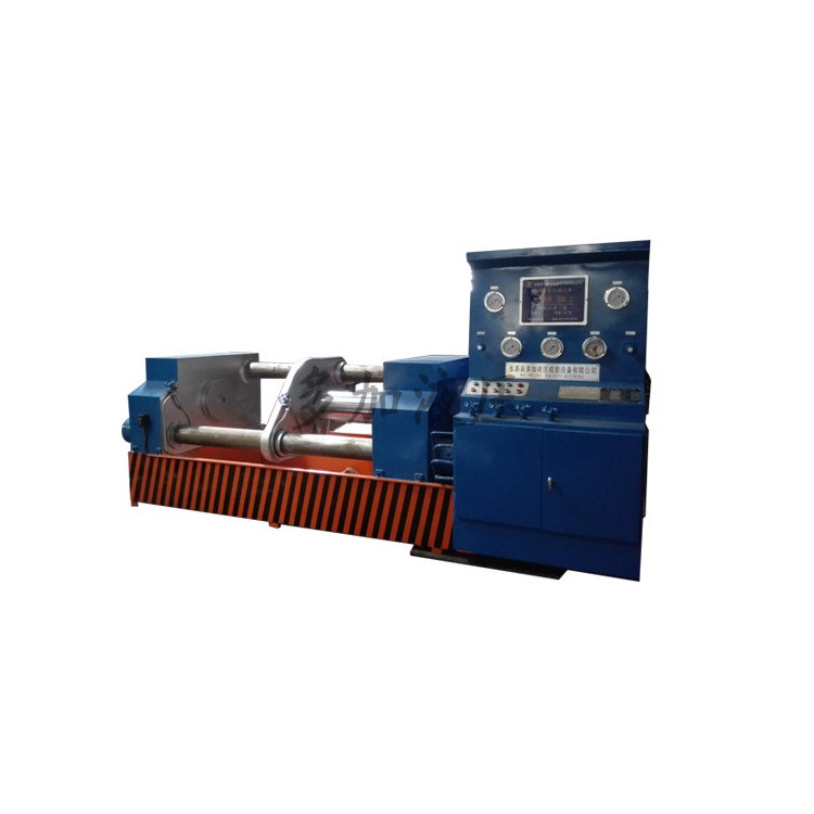


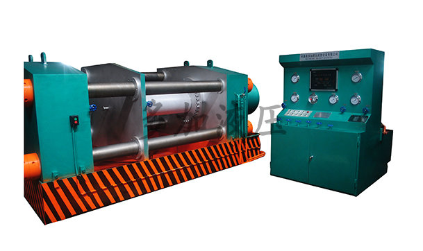
The DYFJ-E1000 valve testing bench is the fourth-generation pressure testing and inspection equipment independently developed by Duojia Hydraulics, based on years of production experience and in accordance with national standards and specifications.
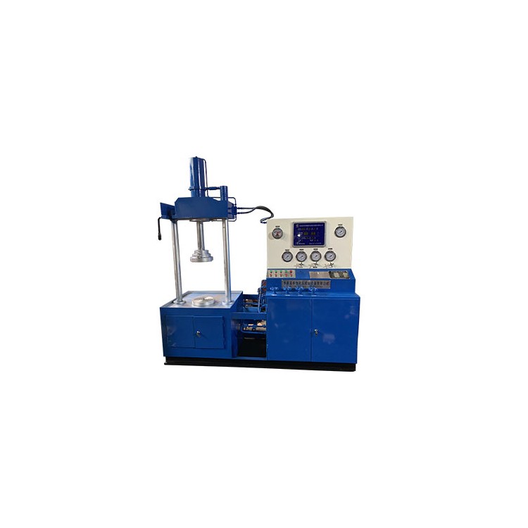
The DYFJ-E1000 type valve test bench integrates mechanical and electrical, hydraulic systems, pressure testing, and the storage and recycling of liquid mediums. It features comprehensive functions, stable performance, and high degree of automation. It is widely used for sealing surface leakage tests and shell strength (pores) tests of various high, medium, and low-pressure valves with nominal bore diameters of 600-1000mm, in the form of straight-through flanges. Test mediums: water, gas, oil.
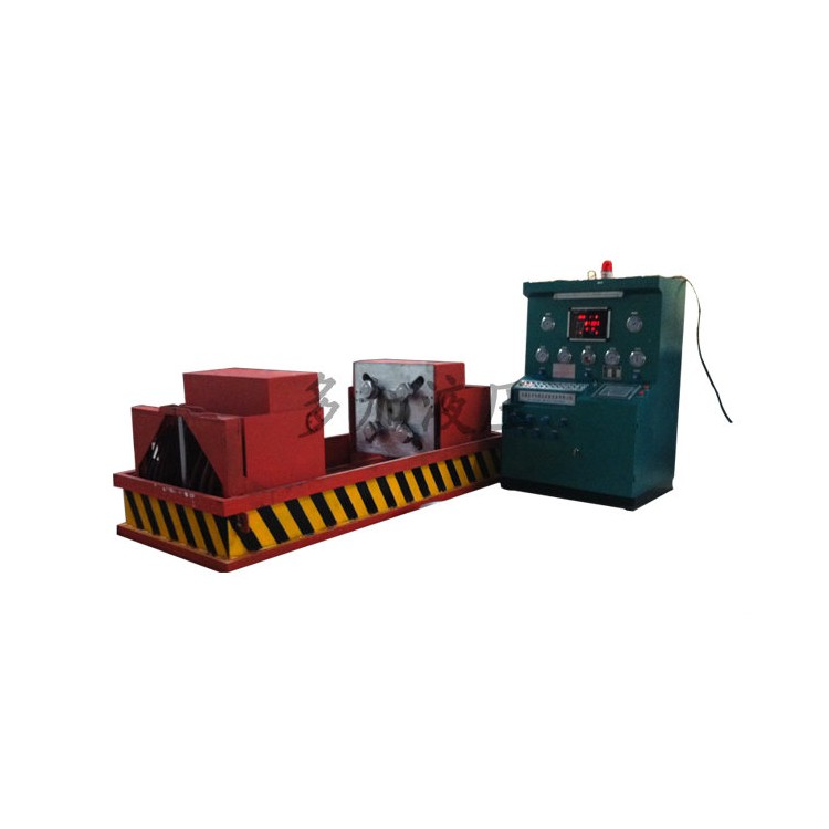
The equipment is hydraulically driven and electrically controlled throughout the process, exerting no additional external forces on valves that could affect test results. This significantly enhances work efficiency and reduces labor intensity, making it an ideal new pressure testing and inspection equipment for valve manufacturing companies, users, and maintenance units.
DYFJ-E1000 type valve test bench working principle and structure
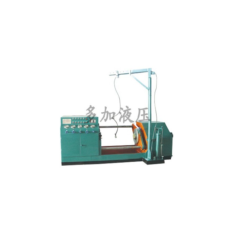
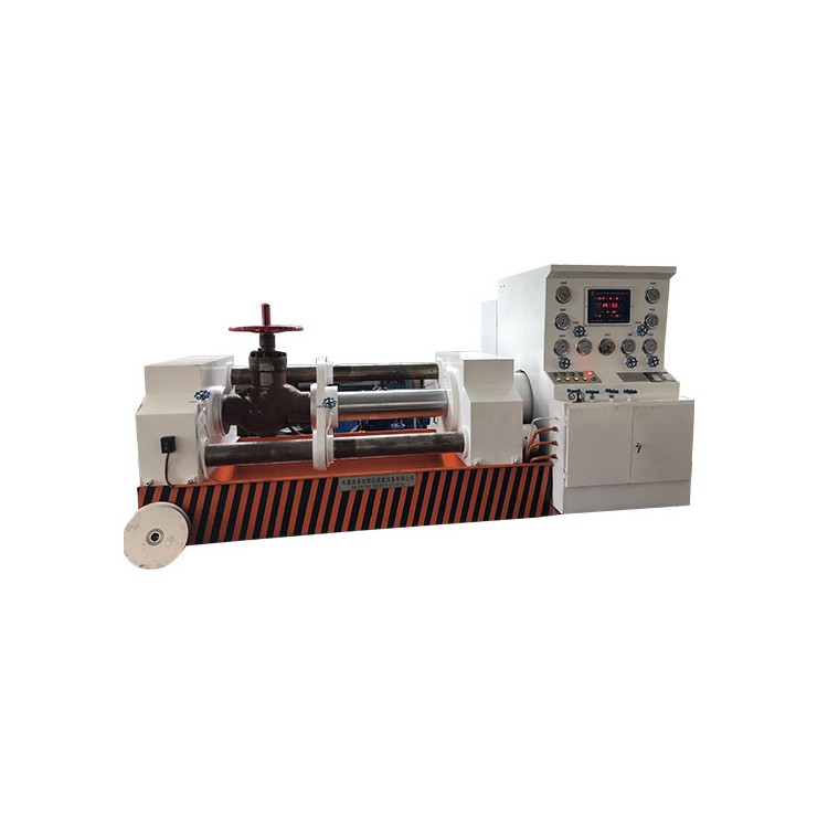
The DYFJ-E1000 type valve test bench operates by positioning the valve flange and clamping the back of the flange with movable claws, ensuring no external forces affect the test results that could compromise the valve testing, in compliance with national standard requirements for valve testing.
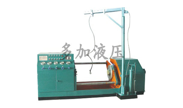
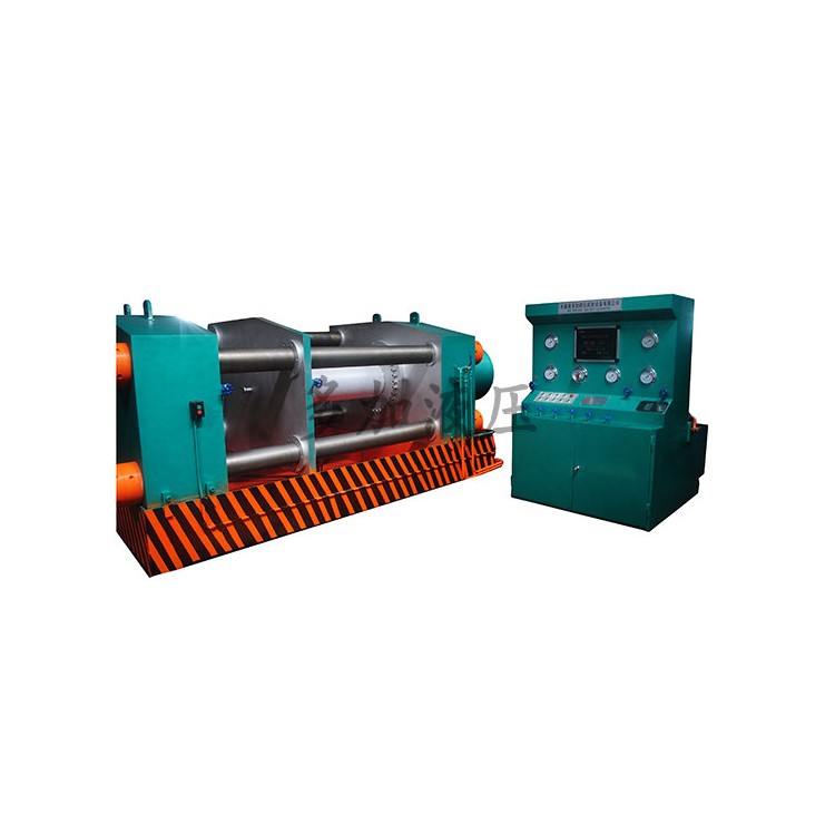
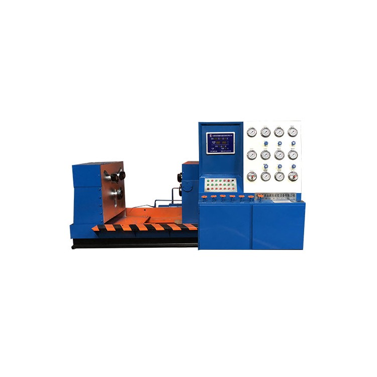
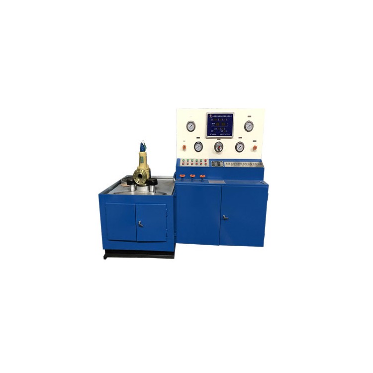
The equipment is broadly categorized into hydraulic pressure supply systems, electrical control systems, water circulation systems, and various operating devices.
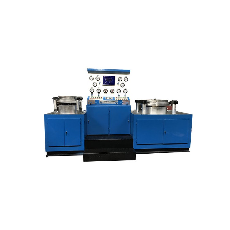
The equipment is a horizontal-top-press type, with both left and right workbenches sealed with blind flanges. The left workbench is equipped with a forward and reverse mechanism, directly driven by a hydraulic cylinder, ensuring even force distribution on the valve sealing surface and reliable tightness. The right workbench is fixed and allows for bidirectional water intake and drainage. The sealing disc is fitted with drain and vent valves, facilitating the inspection of air-sealing tests and the observation of the valve sealing surface. It features excellent performance and a simple, compact structure.
Model | DYFJ-E100 | DYFJ-E200 | DYFJ-E300 | DYFJ-E400 | DYFJ-E500 | DYFJ-E600 | DYFJ-E800 | DYFJ-E1000 | DYFJ-E1200 | |
Valve test bore permitted | DN15-100 | DN50-200 | DN50-300 | DN150-400 | DN200-500 | DN300-600 | DN400-800 | DN600-1000 | DN800-1200 | |
Power Supply | Voltage V | 380 | 380 | 380 | 380 | 380 | 380 | 380 | 380 | 380 |
Frequency Hz | 50 | 50 | 50 | 50 | 50 | 50 | 50 | 50 | 50 | |
Motor | Power kW | 2.2 | 3 | 3 | 3 | 5.5 | 5.5 | 7.5 | 7.5 | 7.5 |
Extreme Number P | 6 | 6 | 6 | 6 | 6 | 6 | 6 | 6 | 6 | |
System Pressure Adjustment Range | 0-6.3 | 0-6.3 | 0-6.3 | 0-6.3 | 0-6.3 | 0-6.3 | 0-6.3 | 0-6.3 | 0-6.3 | |
Highest working pressure of hydraulic cylinder | 31.5 | 31.5 | 31.5 | 31.5 | 31.5 | 31.5 | 31.5 | 31.5 | 31.5 | |
EffectivePlease provide the Chinese content to be translated.Openings (mm) Allowable distance between | 700 | 850 | 1200 | 1300 | 1350 | 1400 | 1600 | 2400 | 2800 | |
EffectivePlease provide the Chinese content you would like translated into American English.Small opening (mm) Allowable distance between | 100 | 170 | 250 | 300 | 350 | 400 | 600 | 1300 | 1900 | |
PumpPlease provide the Chinese content to be translated.High Pressure (MPa) | 63 | 63 | 63 | 63 | 63 | 63 | 63 | 63 | 63 | |
Overall dimensions | L (mm) | 2400 | 2900 | 3300 | 3500 | 3600 | 3700 | 4000 | 5000 | 6500 |
B (mm) | 1100 | 1350 | 1500 | 1550 | 1700 | 1800 | 2300 | 4000 | 5000 | |
H (am) | 1500 | 1500 | 1600 | 1600 | 1600 | 1800 | 2000 | 2300 | 2300 | |
Weight (kg) | 2500 | 3000 | 3300 | 5500 | 7000 | 7500 | 8500 | 45000 | 70000 | |
Operation Instructions
1. Valve Mounting Method
Select a valve with a nominal bore that matches the equipment model, turn on the power, and start the hydraulic system. Move the left-hand cylinder back until it's longer than the tested valve. Place the valve flange face tightly against the right-hand workbench test blind plate, aligning with the center hole. Advance the left-hand moving frame to the right-hand fixed workbench, with the other end of the tested valve pressed against the left-hand test blind plate, aligned with the center hole. The valve is overall in a horizontal position.
2. Water Pressure Testing Methods (Bi-directional Inflow, Drainage)
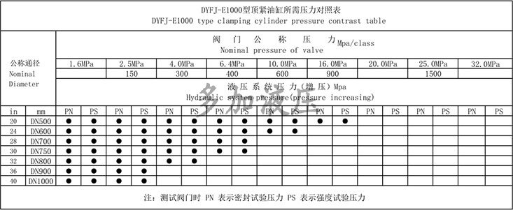
After the valve clamp is in place, refer to the "Clamping Cylinder Pressure Chart" to increase the hydraulic clamp's gripping force to the required pressure. Adjust the electrical contact pressure gauge (for a 25 kg valve, adjust the gauge pointer to 2.5 MPa). Open the main water inlet, left and right water inlet valves, close the air inlet, drain, and vent valves. Start the low-pressure water pump, observe the movement of the water pressure gauge pointer. When the pointer stops rising, it indicates that the valve cavity is filled with water. Start the high-pressure water pump; when the water pressure reaches the set pressure on the electrical contact pressure gauge, the high-pressure water pump automatically stops, and the equipment enters the pressure maintenance state.
Upon reaching the pressure-holding time, the valve is free of any issues. First, open the water valve to relieve the pressure inside the valve chamber, and then remove the valve.
3. Pressure Test Methods (Bi-directional Intake and Venting)
The equipment does not come with a gas source. The user must provide a separate gas source. Please consult the manufacturer before using high-pressure gases.
After the valve fixture is completed (for example, using pressure air, generally not exceeding 10 kg), open the water and air intake valves, and close the water and air exhaust valves. Close the water and air intake valves when the pressure gauge reaches the highest pressure, and the equipment is in a pressure maintenance state.
Upon reaching the pressure-holding time, there are no issues with the valve. It should first be opened to release the air pressure inside the valve cavity, and then the valve can be removed.
Handling Instructions and Requirements
1. Ensure the equipment is level during installation or securely anchor the foot slot with concrete.
2. Choose 46-grade anti-wear hydraulic oil (for temperatures below 0°C, use anti-freeze 46-grade anti-wear hydraulic oil). Ensure oil level is not below the gauge's lower limit. Regularly check oil levels and hydraulic oil. After one year of use, clean the oil tank and replace the hydraulic oil.
3. Add rust inhibitor to the recirculating water, and change the water promptly when the water quality deteriorates.
4. The equipment work surface should be kept clean, and there should be no debris between the test valve flange and the pressure testing blank.
5. All moving parts of the test bench should be lubricated and kept clean for smooth operation.
6. Operators must undergo professional training before taking their posts, ensuring standardized procedures and safety precautions.