





Product Overview
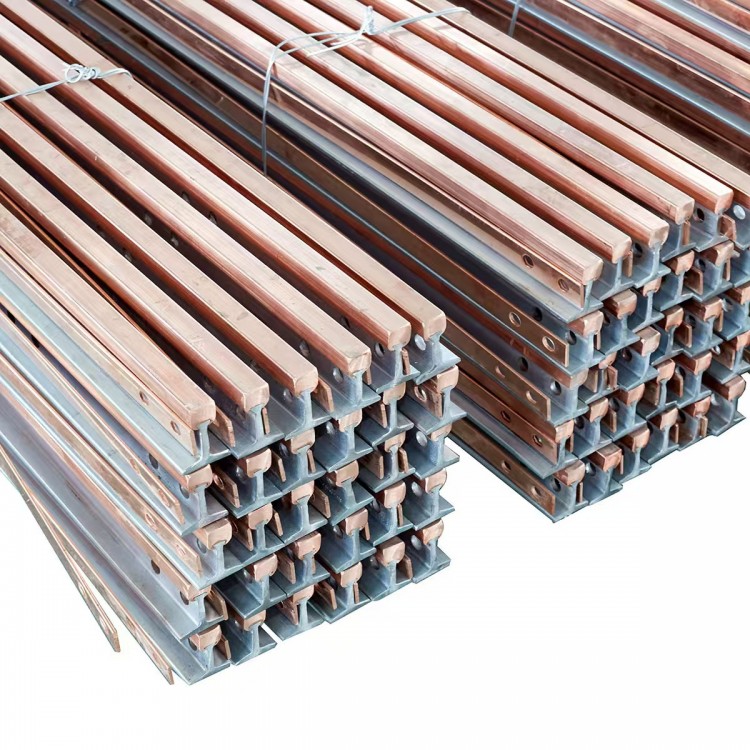
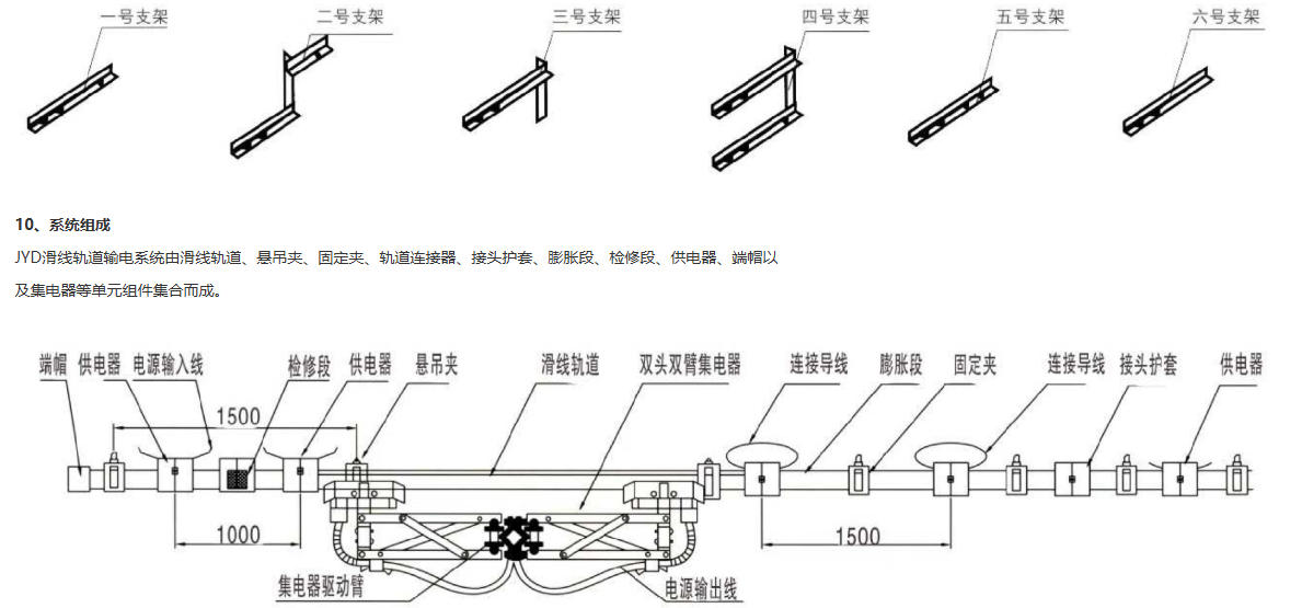
The JYD series monopolar combined busbars are composed of guide rails and sleeves, suspension clamps and support arms, couplings and sleeves, power connectors and sleeves, expansion sections, isolation sections, positioners, end caps and indicator lights, collectors, and drive arms compatible with the collectors. Their structure is rational and simple, with flexible configuration. Additionally, the guide rail materials are high-conductive aluminum alloy or electrolytic copper, and the insulating materials for the sleeves are all carefully selected to offer resistance to chemical corrosion, high-temperature resistance, flame retardancy, and high insulation, making them suitable for harsh environments and high-current operating equipment. Thus, they are widely used in lifting and transportation equipment across almost all industries, as well as in industrial automation logistics conveying systems as one of the main power supply devices. They are suitable for electric bridge cranes in various industries, large and small vehicle electrical connections, mobile power supply for various transportation machinery, loading and unloading bridge mobile power supply, and high-speed power supply for large elevators and hoists. They are particularly suitable for multi-pole power supply, high-speed operation, and high-current applications.
Product Model and Its Meaning
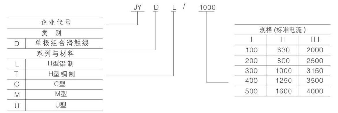
Technical specifications, performance criteria, and specifications
1. Technical Specifications
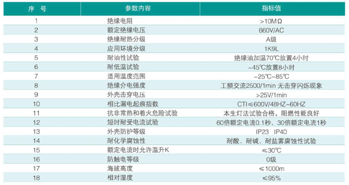
2. Performance Specifications
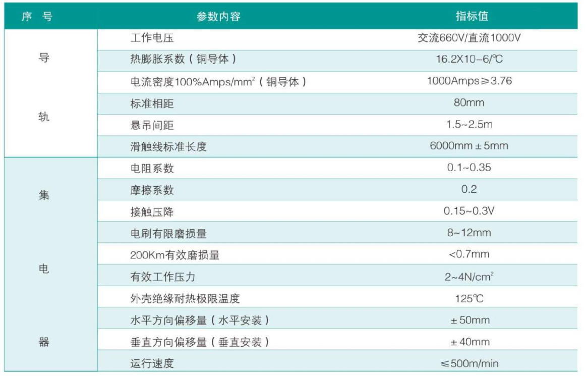
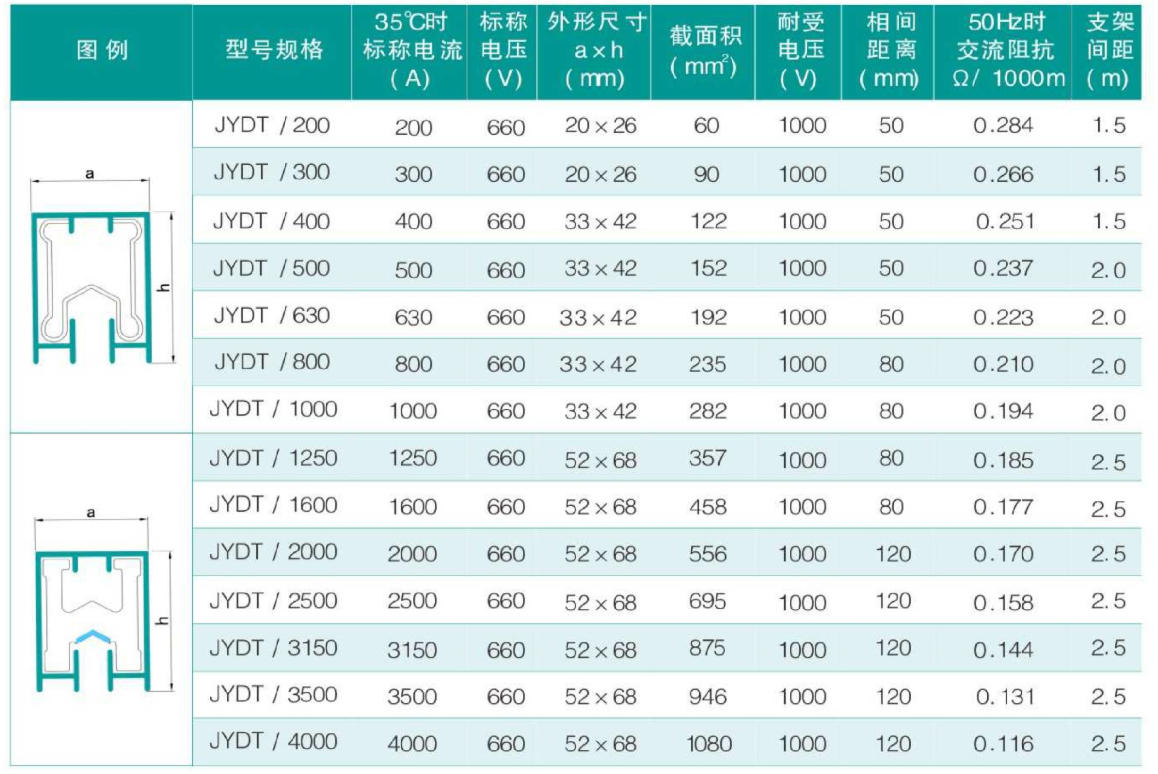
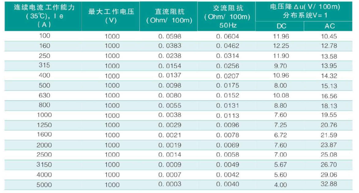
3. Specifications and Parameters
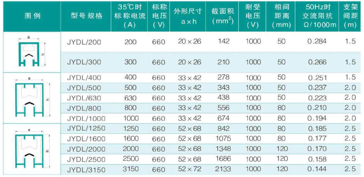
System Composition
1. Guide Rails and Sleeves
· The main material of the sliding contact line, the guide rail body, is made of conductive copper alloy with copper content ≥99.95% to accommodate various usage environments and prevent sulfur dioxide, hydrogen sulfide, acids, alkalis, and chloride ions from salt雾 in coastal areas. It is formed through a rolling process where the mill gradually approaches a single rolling. Due to the cross-sectional design of the guide rail body being "H-shaped," it is commonly referred to as an H-type sliding contact line.
· The grade symbol for conductive copper alloy material is Cu-CATH-1, with a current density of 100 Amps/mm = 1000 Amps3.76, and a tensile strength of over 320-380 N/mm.
The chemical composition of Cu-CATH-1 conductive copper alloy material complies with the standard GB/T5231-2001.
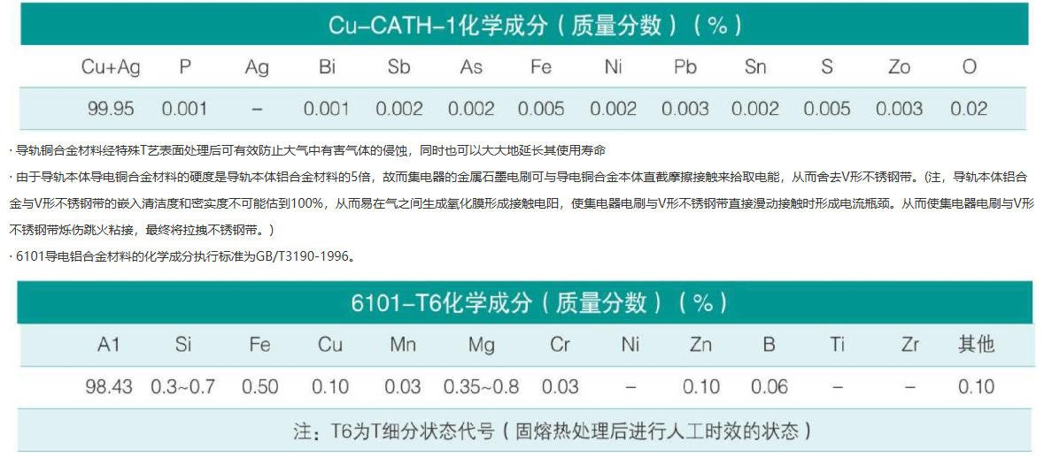
Due to the surface of the aluminum alloy material in the guide rail body not being able to withstand long-term direct friction with the metallic graphite brushes of the collector, the surface where the aluminum alloy material in the guide rail body comes into direct contact with the metallic graphite brush is designed in a V-shape. Subsequently, a stainless steel strip with high conductivity, high rigidity, excellent corrosion and wear resistance is embedded and pressed into the V-shaped groove, thereby creating a monolithic steel/aluminum sliding guide rail body.
· The insulating materials within the slider body system are insulators that lie between the air and the human body, such as the slider guide rail, collector brushes, and other conductive bodies. The quality of these materials directly impacts the insulation performance and overall safety between the insulating shell and the conductive body, as well as the safe operation and lifespan of the entire slider system. Due to the American-ness of the cleaning materials and formulations, many manufacturers are unable to consider the comprehensive performance of the entire insulating material, such as insulation, tensile strength, resistance to aging, corrosion resistance, high-temperature resistance, low-temperature resistance, UV resistance, rainproof, and fire-retardant properties, and instead, they merely pursue breakthroughs in individual performance indicators, resulting in many critical indicators not being achieved in actual use.
· To comprehensively achieve the aforementioned indicators, our company, through nearly a decade of research and development and repeated testing, has finally achieved convincing results in this field. Since the material formula is a trade secret of our enterprise, there is no need to elaborate further. In summary, the matching insulating materials provided by our company, which belong to the polyvinyl chloride, polycarbonate, and ABS series, have directly comparable technical parameters and performance indicators to the protective insulating materials of similar foreign products.
The protective insulation sheath in the sliding wire system is made by extruding through a heating and vacuum shaping process after a scientifically and reasonably formulated mixture of polyvinyl chloride, polycarbonate, ABS, PVC, and auxiliary materials. Therefore, it boasts high mechanical strength, resistance to corrosion from salt mist, acids, alkalis, and organic solvents, as well as excellent electrical insulation and flame-retardant properties, along with good radiation resistance.
· Based on the test report from our company's quality testing center, the indoor service life of JYDL series sliding contact line sleeves is >20 years, and the outdoor service life is >15 years.
2. Electrical Assemblies
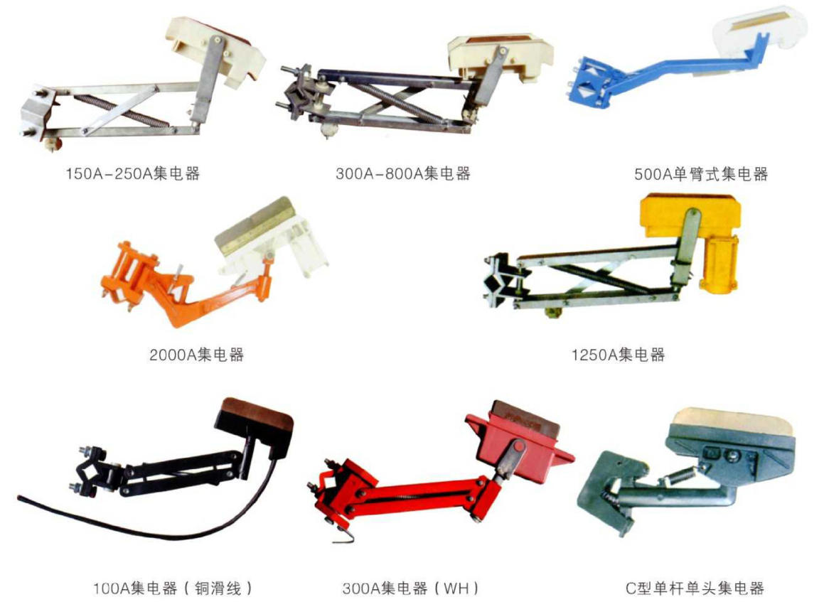
Collectors are one of the main devices in the sliding contact line system that picks up electrical energy from the collection side. They directly conduct electricity to the appliances by means of sliding contact between the collecting brushes and the guide rail, thereby achieving mobile power supply for the system. Collectors consist of two parts: the tension device of the mechanical structure and the collecting brush that directly slides in contact with the guide rail. The tension device of the mechanical structure determines the pressure of the sliding contact between the collecting brush and the guide rail, as well as the stability of the mechanism. The collecting brush, which slides in contact with the guide rail to pick up electrical energy, is the conductor. Its performance, conductivity quality, and material structure composition directly affect the safe operation quality of the entire system. Therefore, the collector is one of the main components in the entire sliding contact line system.
3. Connector (Coupling)
A coupler is a connecting component between guide rails, which not only needs to transmit the guide rail current normally but also bear certain rigidity. Therefore, the quality of the coupler's connection has a significant impact on the entire wire system. It is required that the material of the coupler be consistent with the guide rail material, and its contact resistance should be low. Additionally, the effective contact area of the coupler with the guide rail should be greater than the cross-sectional area of the guide rail to ensure the normal transmission of the entire wire current.
5. Power socket and sleeve
Power supply connectors are the connection components of the sliding contact system, not only supplying electrical power to the guide rails but also ensuring the normal transmission of electricity. They also need to bear a certain amount of rigidity. Therefore, the quality of the power supply connector's connection has a significant impact on the entire sliding wire system. Hence, the material of the power supply coupler should match the material of the guide rail, and its contact resistance should be low. Additionally, the effective contact area between the power supply connector and the guide rail must meet the system's current requirements to ensure the system operates normally.
The sleeve serves as the outer protection and safety insulator for the power supply connector. Its crucial role in the entire system is self-evident, and it will play a decisive role in the safe operation of the system. Therefore, the quality of the sleeve directly impacts the entire system's safe operation. Hence, the requirements for the sleeve material are critical. We must control and standardize the material's corrosion resistance, high-temperature resistance, and flame retardancy.

6. Expansion Segment
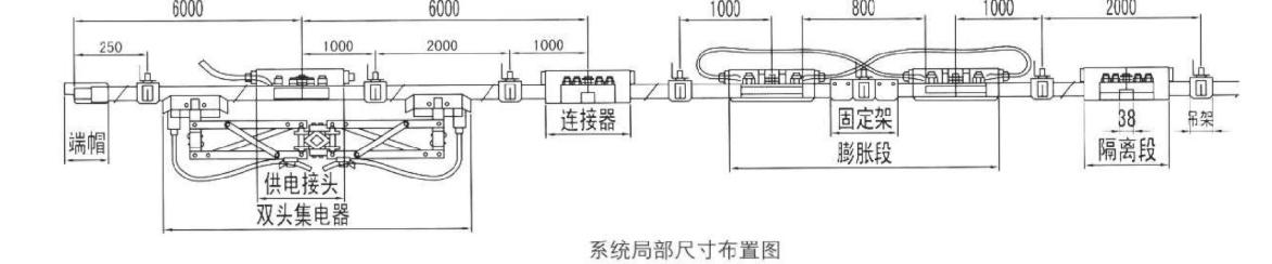
The expansion section is designed to prevent power failure due to the linear deformation (profile extrusion) and contraction (profile shrinkage) of the sliding contact wire when it operates in different temperature environments. It consists of two movable sections connected in series directly with the wire body, forming a transition body that fits the cross-section of the sliding contact wire. This allows for free linear movement in response to changes in the sliding contact wire's environmental temperature. Due to the stacking of the static and dynamic slabs, it provides a straight-line transition plane for the collector brush, overcoming the narrow expansion range of older expansion terminals. This eliminates issues such as difficulty in bridging, reduced contact surface causing sparks, and other problems. As the static and dynamic slabs are directly connected to the wire body and guided by two sliding rods, it maintains good coaxiality. Additionally, two soft cables parallel to the sliding contacts are set at the ends of the static and dynamic slabs, stabilizing and increasing the current carrying capacity of the expansion section, ensuring that the entire system's rated current carrying capacity is not affected by the presence of the expansion section.
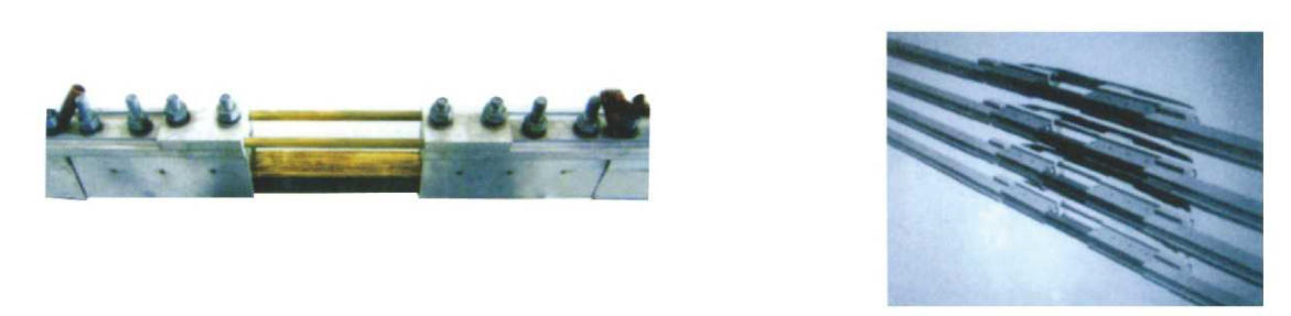
7. Maintenance Section
The isolation section is a device in the sliding contact system used for isolating trains or other equipment during online maintenance. It isolates a power rail into one or several sections, thereby enabling the normal operation of multiple trains or other equipment on the same rail system.

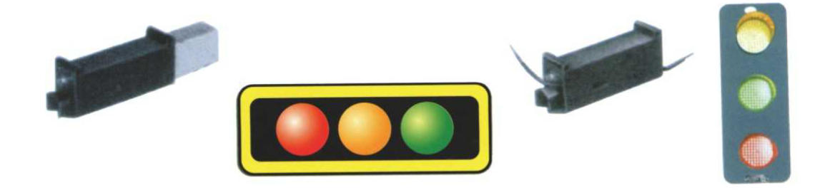
8. End Caps and Indicator Lights
End caps and indicator lights are the terminal devices for the slider track system, providing both closure protection for the ends of the slider track and power indication for the entire system. The indicator lights are composed of LED light-emitting diodes, available in yellow, green, and red colors, with a flat cylindrical structure. Due to the use of LED technology, these indicator lights feature low power consumption, high luminous efficiency, and long lifespan, making them suitable for all-weather operation indoors and outdoors.
Drive Arm
The drive arm is the mounting carrier for the electrical collector and is directly fixed to the system's moving device, thereby achieving sliding contact between the collector and the guide rail. The selection of the drive arm depends on the structural form of the equipment and the collector, and its stiffness and the tension of the force arm also need to be considered in the selection of the drive arm. Therefore, the structural form and material requirements for the drive arm are also significant.

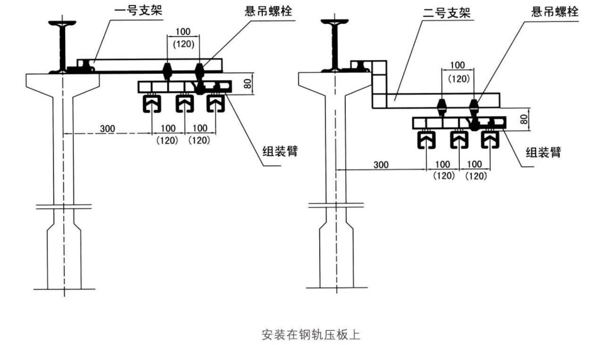
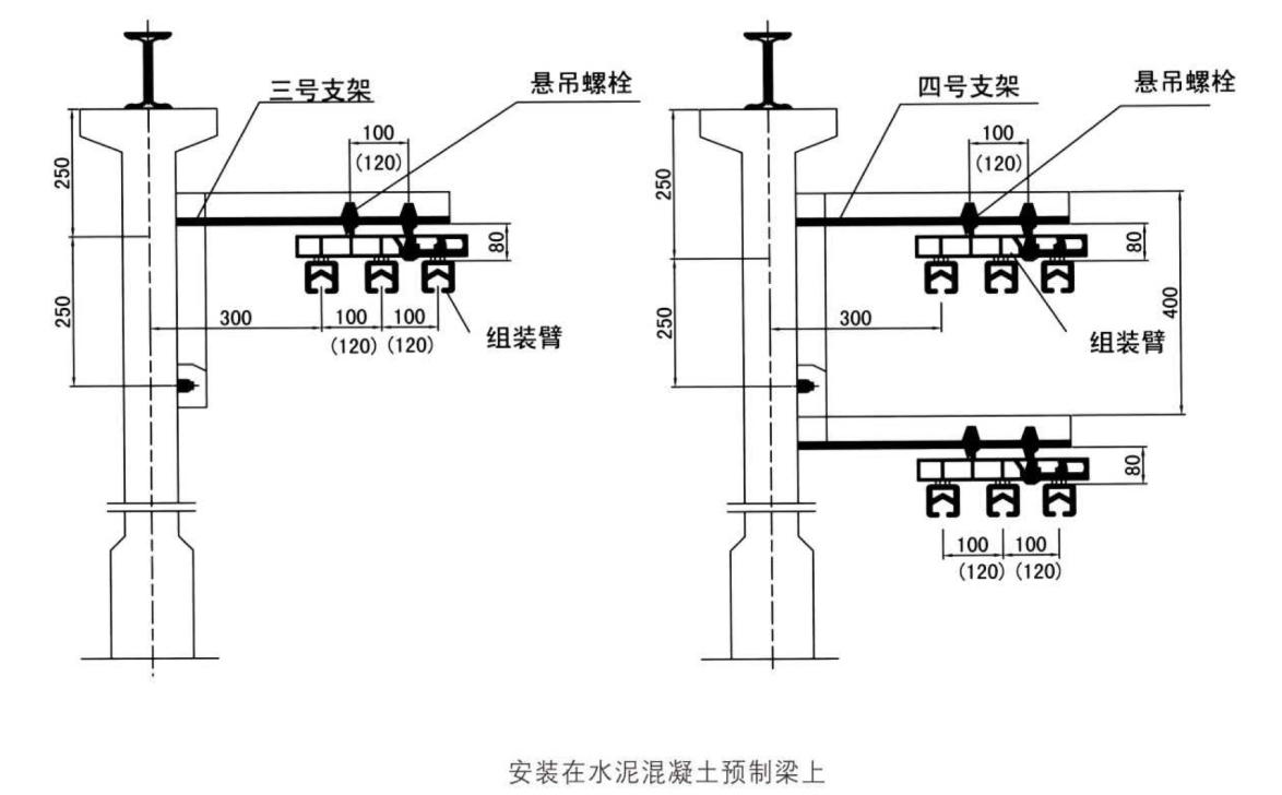
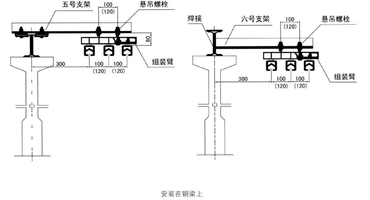
9. Installation Bracket (Suspended Bracket)
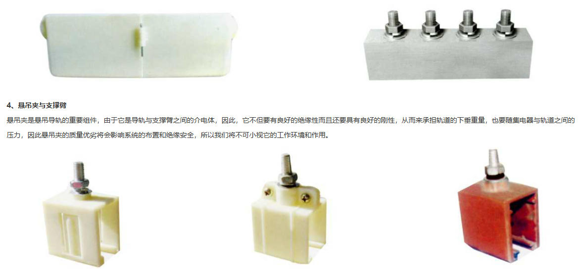
Hanging Bracket: A structural unit for the hanging assembly arm, installed on the water mixed precast component or beneath the steel rail deck.
11. System Installation
System Selection and Calculation
1. Selection
Selecting a mobile power supply system is a scientific calculation process, involving numerous factors such as the on-site environment, altitude, average annual temperature, the duration of power consumption by appliances, the nature of the appliances, power voltage, frequency, and power factor. Therefore, it is a rational quantitative calculation process and should not be estimated roughly. Doing so is neither safe nor economical, and in severe cases, it can lead to the system being scrapped.
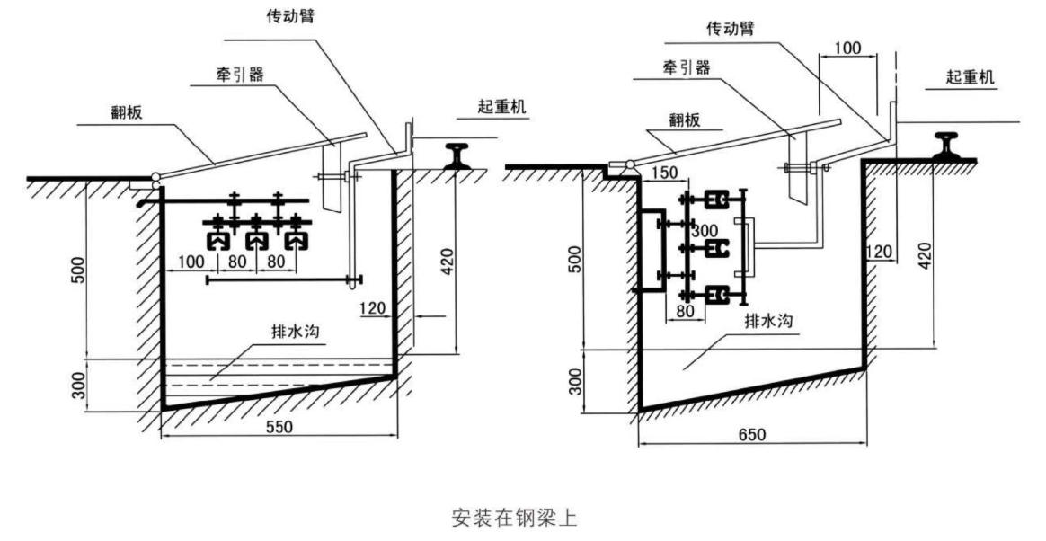
· Based on the usage environment and the structural arrangement of the on-site operating equipment, select the structural and installation type of the busbar, as well as the usage environment of the busbar—indoor or outdoor. Additionally, confirm whether it's an overhead架空 type or a trough type for outdoor applications.
Once the structural form of the busbar is determined, select the environmental temperature of the outer insulator for the busbar based on the usage environment—whether it's low-temperature, ambient-temperature, or even high-temperature. For special applications, the outer insulator may not be required.
· Once the structure of the sliding contact wire and the outer insulator are confirmed, the conductor material for the sliding contact wire must be determined based on the investment意愿, i.e., whether it should be copper or aluminum. The former has higher initial investment costs than the latter, but offers advantages such as smaller size, longer lifespan, lower electrical resistance, and reduced voltage drop. The latter, due to the inherent differences between aluminum and zinc, has lower physical properties compared to the former, but its initial investment cost is definitely lower. Therefore, users need to consider and determine based on a comprehensive evaluation of cost-effectiveness, safety, and reliability.
After considering the aforementioned factors, conduct a statistics of the power load of the system equipment to calculate and determine the conductor current of the slip ring.
· Selection of conductor and sliding contact wire cross-sectional area
Properly selecting the cross-sectional area of conductors and sliding contacts ensures the normal operation of the power supply network and load, conserves non-ferrous metals, and reduces energy loss.
The selection of wire and busbar cross-sections should meet the following aspects:
The heat generated by the load current passing through conductors and slides over a long period of time should not overheat to damage the insulation and cause accidents such as short circuits and fires.
The wire should have sufficient mechanical strength to prevent it from being pulled apart due to factors such as wind force, weight of snow and ice, etc., which could lead to power supply interruptions and other safety hazards.
The voltage drop in the lines should not be excessive (as per the crane design specifications: for AC power supply, the voltage drop from the low-voltage bus side of the self-powered transformer to any motor terminal of the crane during peak current should not exceed 15% of the rated voltage. For general bridge cranes with a lifting capacity of 32 tons or less, the voltage drop within the crane should not exceed 5% and externally should not exceed 10%; for lifting capacities greater than 32 tons, the voltage drop within the crane should not exceed 4% and externally should not exceed 11%).
· Conductive and sliding contact lines' heat generation is calculated based on working current. Voltage loss is calculated for high current, thus it is necessary to master the calculation methods for both working and high currents.
(1) Calculation of Working Current
The working current of the wires and busbars for a single motor is the rated current of the motor (at the reference power factor). If a mechanism is driven by several motors simultaneously, the working current of the wires and busbars supplying that mechanism should be the sum of the rated currents of all the motors in the mechanism.
When calculating the total working current of the entire crane, since all mechanisms do not usually operate simultaneously, the total working current can be calculated using either of the following two methods.
(1) Calculate the rated current of the motor based on the sum of the three possible working institutions, with one institution's motor power being the largest among all institutions: lg = le1 + le2 + le3 (5-5-1)
Equation: Ig ---------- the working current of the conductor or sliding contact wire (A)
Ie1----------Total rated current of all motors in high-power machinery (at reference duty cycle) (A)
Ie2, Ie3 ---------- Rated current of the motor (at rated power factor and under continuous duty cycle) (A) in the other two possible operating agencies.
For cranes with smaller capacities and fewer protective boxes, the working current is typically calculated using the above formula.
(2) Calculated by power, i.e., Ig = K1N + KN + Ik (5-5-2)
Equation: N3------------------The total power (kW) of three high-power units at the reference power supply continuity rate.
Total Power (kW) of all motors in the entire crane at the rated power factor:
K1, K2----------------Coefficient (A/kW)
lk---------------------Operating current for control circuits, brake actuators, lighting, etc., typically 15A.
For cranes with larger capacities and multiple installations, which commonly use a main power distribution box, the working current is typically calculated in this manner. The calculated working current represents the equivalent long-term working current, and the wire or cable conductor cross-section should be selected based on the long-term load carrying capacity allowed for the conductors.

(II) Calculation of High Current
High Current, also known as Peak Current. The high current supplied to the wires and conductors of a single motor is calculated based on the motor's starting current. Current for a specific mechanism of the crane.
1zd=Kle (5-5-3)
lzd---------High Current (A):
K-------Motor starting current multiple, for wound rotor motors, generally take 2 or actual multiple (1.8~2.3). For squirrel-cage motors, refer to the product catalog; for crane DC motors, take 2~2.5.
Total rated current of all motors in the actual power-on duration of the facility (A).
When calculating the current for an entire crane or multiple units, various factors are taken into account, often using the following calculation methods.
(1) When considering all three agencies working simultaneously, the motor of the power agency is starting up, while the motors of the other two agencies that may be working at the same time are in normal operation, i.e., 1zd-K11+12+163 (5-5-4)
In the formula: lzd-----The sum of the rated currents of all electric motors in the power unit of the entire crane (at actual connected power factor)(A).
le2, 1e3 -- Rated current of the motors in the other two institutions that may be operating simultaneously (A, under actual continuous power supply rate).
(2) When considering different factors indoors and outdoors, calculate using the following formula: lzd-K1le1+Kose (5-5-5)
Equation: K1 ------------ Times of motor starting current, same as in Equation (5-5-3)
K2 - Coefficient, 0.8 for overhead cranes indoors; 0.6 to 0.7 for outdoor cranes.
The sum of all rated currents from other agencies that may be used simultaneously (A), under actual power connection duration (A).
The internal wiring of cranes is generally not very long. When selecting the wire cross-section based on heat generation, the voltage loss is usually within the allowable limit. Therefore, when choosing the wire cross-section, first select the cross-section based on the wire's allowable current being greater than the circuit's operating current, and then inspect it according to the mechanical strength requirements of the wire. For the external wiring of cranes, after selecting the wire cross-section based on heat generation, the voltage loss should be checked for accuracy.
From the standpoint of mechanical strength, the wiring on the crane must use multi-strand single-core conductors with a cross-sectional area of not less than 1.5mm² and multi-strand multi-core conductors with a cross-sectional area of 1mm². Wires, cables
The voltage loss of copper conductors is calculated according to the following formula:
Three-phase AC Load AU = 173lzdLcosφ/6qUe (%) (5-5-6)
Direct Current Load Au=200lzaL/6 qUe(%), where: L- (5-5-7)
Equation: L ------------ Calculated length of wire, cable, or conduit (m)
Power Factor (cosφ) - The power factor of the load, 0.65 for wound-type motors; 0.5 for squirrel-cage motors.
U——Rated Voltage of Power Grid (V):
Conductor cross-section or copper wire cross-section (mm)
Conductivity of wire materials (m/Q·mm): Copper at 50 (reference wire core temperature +60°C), Aluminum at 35, Steel at 6.05.
Simple calculation for voltage drop of sliding contact line
1. Communication Equipment: Voltage Drop Length x Impedance x Current x 1.732 2. DC Equipment: Voltage Drop Length x Resistance x Current x 2.00
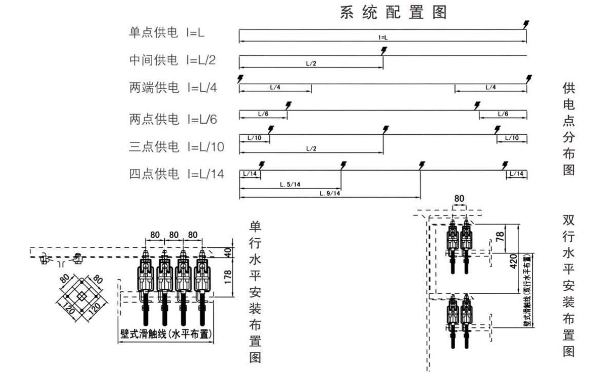
Note 1: Terminal Power Supply: Calculation Length L for Voltage Drop
Intermediate Power Supply: Calculation Length for Voltage Drop L/2
Two-Way Power Supply: Calculation Length for Voltage Drop - L/4
Power supply at both ends, 6L from center: Calculated length for voltage drop - L/6
Supply at the L/10 position from both ends: Calculation Length L/10 for Voltage Drop
Note 2: General starting current for motors
Standard squirrel-cage motor with 5 times the normal operating current
Conical motor (electric hoist) 7 times the normal operating current
Sleeve-type motor with twice the normal operating current
Note 3: Effective methods to reduce voltage drop
Modify the location of the system's power supply point or reduce the length of the system's non-effective operation
Select high conductivity sliding contact wire body conductive materials (copper or aluminum).
System Installation Diagram
After the initial operation of the entire overhead transmission system for four to five weeks, it is necessary to shut down the power to make corrections and reinforce the mechanical structure, electrical performance, and other related components to ensure the reliable and safe operation of the system.
· Pay attention to timely replacing worn-out brush strips during the operation of the collector, and do not arbitrarily alter the brush material or reduce the cross-sectional area of the brush strips.
Due to the long-term operation of the system and the influence of environmental temperature, dynamic components such as the expansion section, air-insulated section, sliding track connector, and collector must be regularly adjusted and secured to ensure good electrical contact performance.
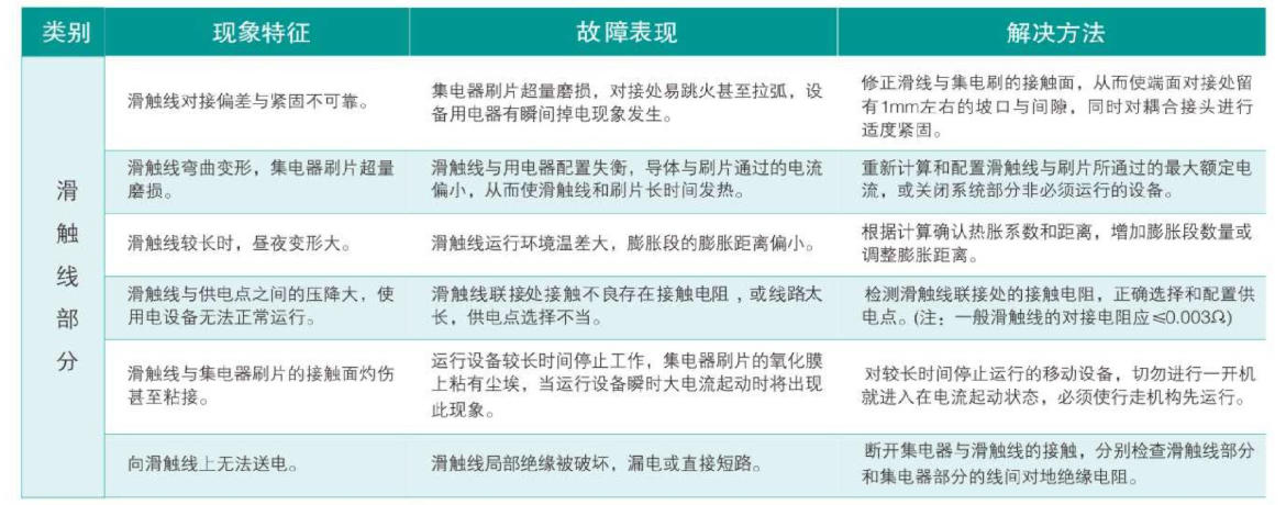
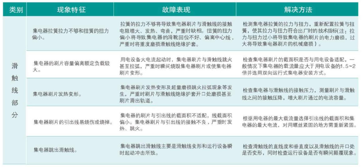
· The system must undergo regular maintenance and care, and must not operate with faults or potential hazards, to ensure the safety of both the system equipment and personnel.
Installation Type