


I. Scope of Application
The JYMM series compact insulated busway is suitable for power distribution systems with rated voltages below 690V, rated working currents of 100~5000A, and frequencies of 50~60Hz.
II. Structural Performance
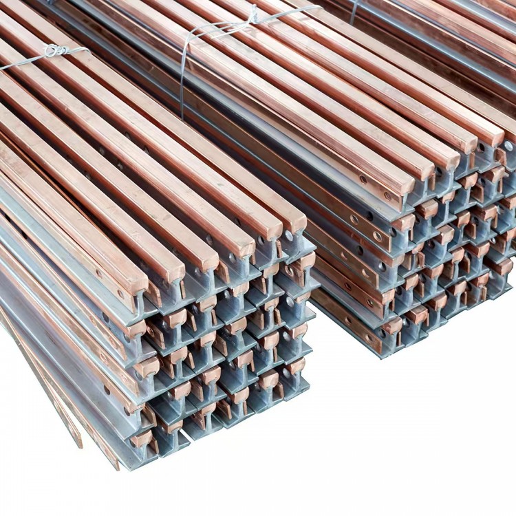
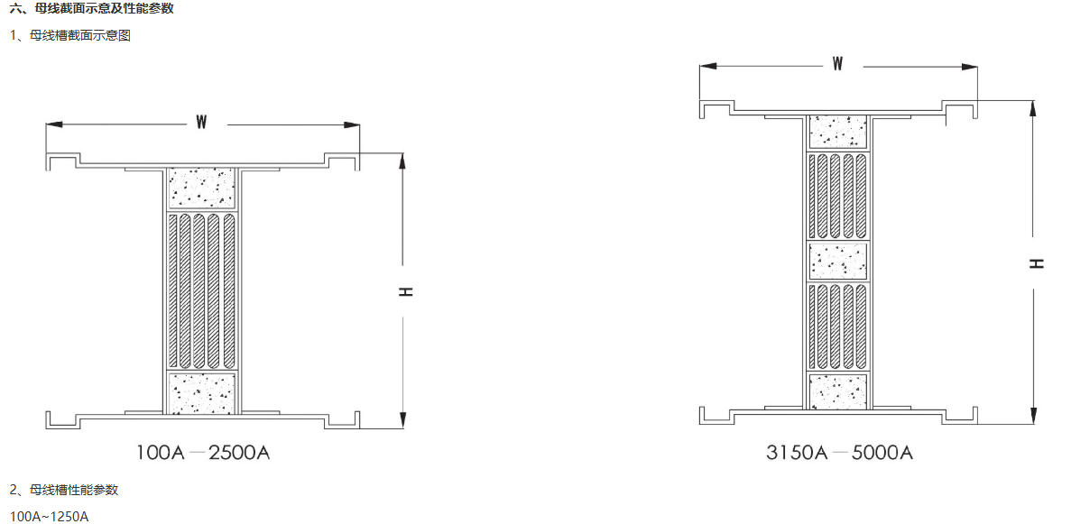
Utilizing a rational "sandwich" phase line tightly overlapped structure design, the busbar channel achieves a more compact shape and smaller volume, enhancing the dynamic and thermal stability of the busbar system. This results in lower impedance and reduced voltage, effectively preventing the formation of "chimney effect" in busbar channels during fires. Suitable for large-span installations at construction sites.
The housing is composed of a mix of die-cast electrical aluminum profiles and cold-drawn thin steel profiles (also available with reinforced all-aluminum alloy structural profiles). This housing is lightweight, fully enclosed, and non-ventilated, combining the high strength of steel with the excellent corrosion resistance and heat dissipation of aluminum. The special weakly magnetic aluminum side panels can reduce the eddy current phenomenon between large current busbars, minimizing the heating caused by eddy currents in the busbar conductors, significantly enhancing the busbar's current carrying capacity. It also forms an integrated grounding system within the housing, effectively alleviating the pressure on the busbar PE grounding bars during large capacity grounding faults. This serves as a secondary grounding system in the form of double insurance, ensuring the safe operation of the entire busbar system.
Equipped with a standard configuration single arm lock tension shock absorber connector, offering reliable and convenient connection.
Feeding power sockets can be conveniently set on both top and bottom surfaces without reducing their bending strength. The safety protection level of the feeding power sockets reaches IP54 (compliant with standard EC529). Each socket set is equipped with a custom-made locking mechanism to prevent dirt, dust, and incorrect operation. The material is ABS engineering plastic.
Section 3: Insulation Configuration
The JYMM series compact insulated busbar uses insulation material polyimide film (DuPont Mylar) as its main insulation medium. This material boasts excellent high-temperature resistance (no toxic gases released at high temperatures), high dielectric properties, and an insulation grade of "B." Alternatively, the material polytetrafluoroethylene定向film SFM-3, known as the "Plastic King," can also be used. This material has an extremely high temperature resistance (-180°C to +250°C), a single-layer voltage of 6000V, an insulation grade of "C," and an insulation aging life of over 50 years, making it one of the best-performing insulation materials currently in use.
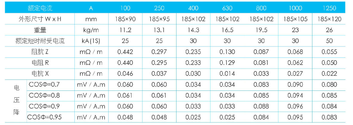
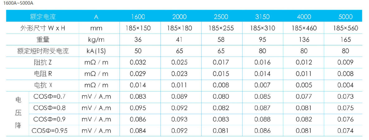
IV. Main Technical Parameters
Utilizing a "sandwich" sealing structure design, general protection ratings are IP42, IP54, with special requirements up to IP65.
The busbar system can withstand a working frequency withstand voltage of 3750V, with no breakdown or flashover occurring for 1 minute.
The busbar system, when operating continuously at the rated current, its temperature rise does not exceed: at the connection terminals: 60K, on the metal housing: 30K, on the surface of the insulating components within the slots: 40K.
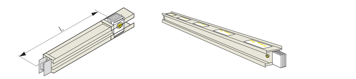
1. Linear Segment Unit
The dense insulation busway housing structure is completely sealed, with a high protection grade up to IP65, suitable for use under harsh conditions. The system selects the entire housing with more than 50% of the phase wire capacity as the grounding system to ensure sufficient safety, providing a reliable grounding path for grounding faults and a short path for grounding faults. In the event of a high-capacity grounding fault, it can effectively ground and protect the entire system. The feeder busway can be installed vertically or horizontally.
Standard Length: L=1, 2, 3, 4 meters
Optional Length: L=0.5~3.99 meters
The busbar trunking system can be installed vertically or horizontally, offering flexible socket placement on both sides. The small spacing between sockets is 575mm. Users can reserve sockets according to specific conditions, ensuring that the busbar trunking units can still accommodate load changes or additions in the future, providing a safe, reliable, and convenient power supply environment for customers.
Standard Length: L=1, 2, 3, 4 meters
Optional Length: L=0.7~3.99 meters
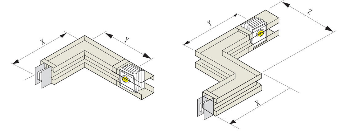
2. Directional unit
L-shaped horizontal elbow, convenient for changing the direction of a section of busbar, rated current 100A~5000A
Standard Length: X=0.35m or X=0.5m; Y=0.35m or Y=0.5m
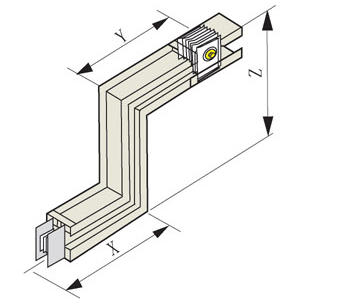
Z-shaped horizontal elbow Standard length:
X=0.35m or X=0.5m
Y = 0.35 m or Y = 0.5 m
Z=0.35m or Z=0.5m
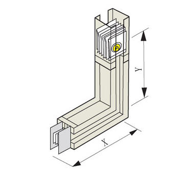
L-shaped vertical elbow
Standard Length:
Rated Current: 100A~2500A
X/Y = 0.35m or X/Y = 0.5m
Rated Current: 3000A ~ 5000A
X/Y = 0.50m or X/Y = 0.8m
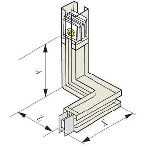
Z-shaped vertical bend
Standard Length:
Rated Current: 100A ~ 2500A
X/Y/Z = 0.35m or X/Y/Z = 0.5m
Rated Current: 3000A ~ 5000A
X/Y/Z = 0.50m or X/Y/Z = 0.8m
Odd-shaped elbow
Standard Length
Rated Current: 100A ~ 2500A
X/Y/Z = 0.35m or X/Y/Z = 0.5m
Rated Current: 3000A to 5000A
X/Y/Z = 0.50m or X/Y/Z = 0.8m
Tee Elbow
Standard Length:
Rated Current: 10A~2500A
X/Y/Z = 0.35m or X/Y/Z = 0.5m
Rated Current: 31A ~ 5000A
X/Y/Z = 0.50m or X/Y/Z = 0.8m

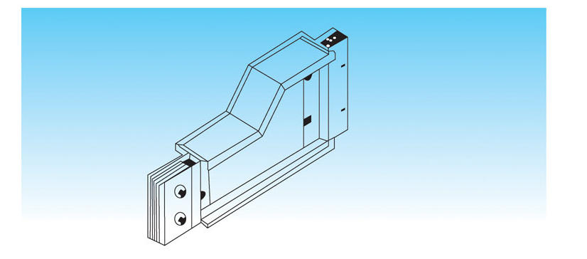
3. Variable Capacity Unit
Convert current from high to low amperes, providing users with a more economical transmission environment.
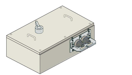
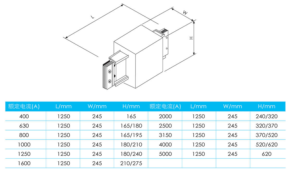
4. Soft Connectors
Busbar unit can be connected to transformers of different specifications and models via soft connections; the maximum current it can handle is 5000A. Our company provides complete soft connection units, which prevent loose fasteners due to transformer vibration, thereby affecting the operation of the entire power distribution system. Additionally, the design can be adjusted according to the specific transformer wiring, maintaining the shortest path and time for on-site connections. Furthermore, our company offers separate cabinet top box units to prevent the exposure of live components, enhancing the system's protection level and safety performance.
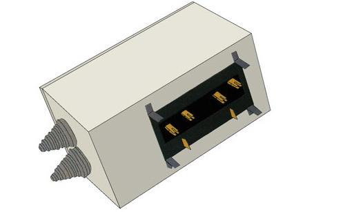
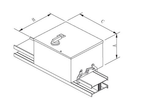
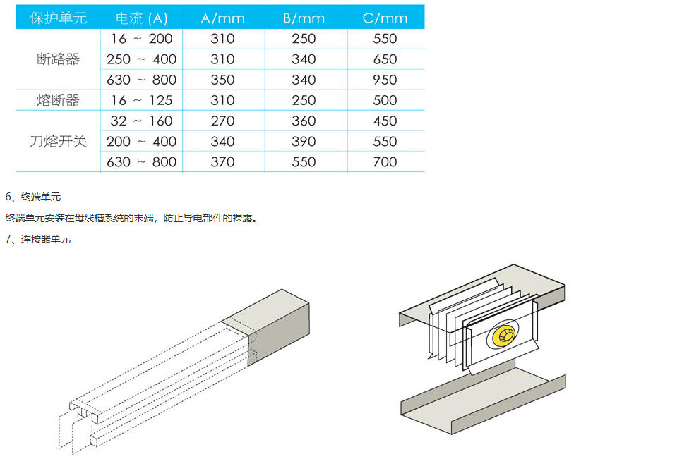
5. Connector Unit
(1) Briefly describe
Busbar channel units can be set up with interfaces on both sides, offering flexible interface arrangements. Each standard linear segment unit can accommodate up to 10 interfaces, with a minimum spacing of 575mm between the interfaces.
Rated working voltage is 690V.
Protection ratings: IP42, IP54.
There are three protection methods:
The model of circuit breakers with protection current ranging from 16A to 800A can be selected by the user themselves.
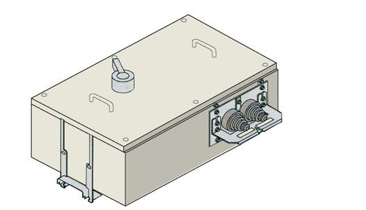
2. Protected with a fuse, current range is 16A to 125A.
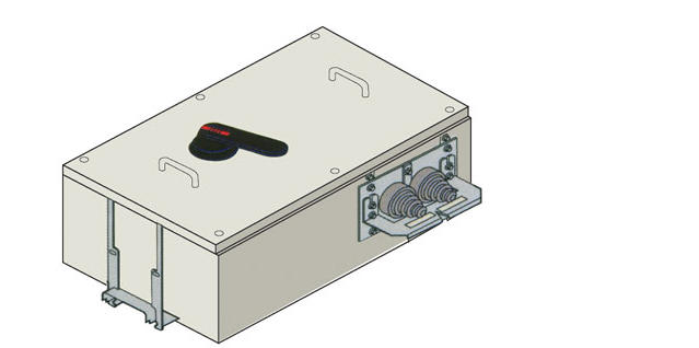
3. Equipped with knife switch protection, current range is 32A to 800A.
Silver-plated pins to ensure electrical continuity of the system. Unique anti-mismatched phase connection: the built-in positioning system on the connector box effectively enhances anti-mismatched phase capability.
(2) Safety Protection for Connector Boxes
The automatic safety cover on the plug socket boasts a high protection level, ensuring that installers and maintenance personnel never come into contact with live conductors at any time, and allows the busway system to be used in various harsh environments without the need for special sealing devices.
(3) Internal Interlock of the Socket Box
The junction box is equipped with an internal interlock mechanism to prevent the door from being opened when power is on, further ensuring the personal safety of the operators.
(4) Three Types of Protection for Connector Boxes
Circuit breaker protection junction box
· Rated Current
Circuit breaker protection, rated current: 16A to 1250A.
·Interlock
The junction box includes interlock mechanisms to prevent disassembly of the busbar plug-in junction box while in the connected position.
· Configuration
Based on the customer's configuration requirements for the junction box, 3-pole or 4-pole circuit breakers can be installed inside the box to protect the load. The circuit breaker models can be selected by the customer, including accessories for the protective switch such as operation handles, auxiliary release, thermal magnetic release, and leakage protection modules. Our company provides standard configurations according to the customer's specifications. Additionally, we can design non-standard dimensions for the junction box based on on-site measurements and specific conditions to meet on-site requirements.
· Cable connection
The junction box supplies power to the load by conducting current through cables. A specialized cable protection sleeve is configured at the cable outlet, with the diameter of the sleeve adjustable according to the cable's diameter.
Circuit Breaker Protection Connector Box
· Rated Current
Circuit breaker protection, rated current: 16A~125A.
· Interlock
The junction box features interlocking devices to prevent the disassembly of the busbar plug-in box when it is in the connected position.
· Configuration
Based on customers' requirements for the connector box configuration, fuses can be installed inside the box to protect the load, and our company offers standard configurations. Additionally, we can design non-standard dimensions for the connector box according to the specific on-site conditions after measuring on location, to meet on-site requirements.· Cable Connector
The junction box supplies power to the load via cables, featuring a dedicated cable protection sleeve at the cable outlet. The diameter of the protection sleeve can be configured according to the cable's diameter.
③ Blade Melt Switch Protection Connector Box
· Rated Current
Blade fuse switch protection, rated current: 32A ~ 800A.
· Interlock
The junction box features interlocking devices to prevent the disassembly of the busbar junction box when it is in the connected position.
· Configuration
Based on the customer's configuration requirements for the junction box, fuse switches can be installed within the box to protect the load. Our company will provide standard configurations as per the customer's specifications. Additionally, we can design non-standard dimensions for the junction box's appearance after on-site measurements, tailored to the specific on-site conditions to meet the requirements.
· Cable connection
The junction box supplies power to the load by conducting current through cables. A dedicated cable protection tube is configured at the cable outlet, with the diameter of the protection tube adjustable according to the cable diameter.
(5) Connector box dimensions
· Disregarding traditional design, installation speed is twice as fast as with standard connectors.
· Special double-head torque single bolt easily controls the clamping force required for the connection unit, ensuring the joint pressure.
· The connection fits naturally, without generating mechanical stress. All bolts and washers are made of steel with electroplated coatings that offer sufficient strength and toughness. The connection cover with insulating pads ensures a high protection level at the busbar connection as well.
· No torque wrench required for installation; a standard 19mm wrench is sufficient to meet the installation requirements. Installation is easy and user-friendly.
· Due to its non-reversibility, it offers enhanced safety, and its asymmetry prevents phase mismatch during busbar connections.
· The design of the connector (plug-in type) accommodates the linear expansion of the busway due to expansion, providing each connector with 7mm of expansion compensation without compromising the mechanical strength, electrical continuity, current carrying capacity, or short-circuit current of the busway.
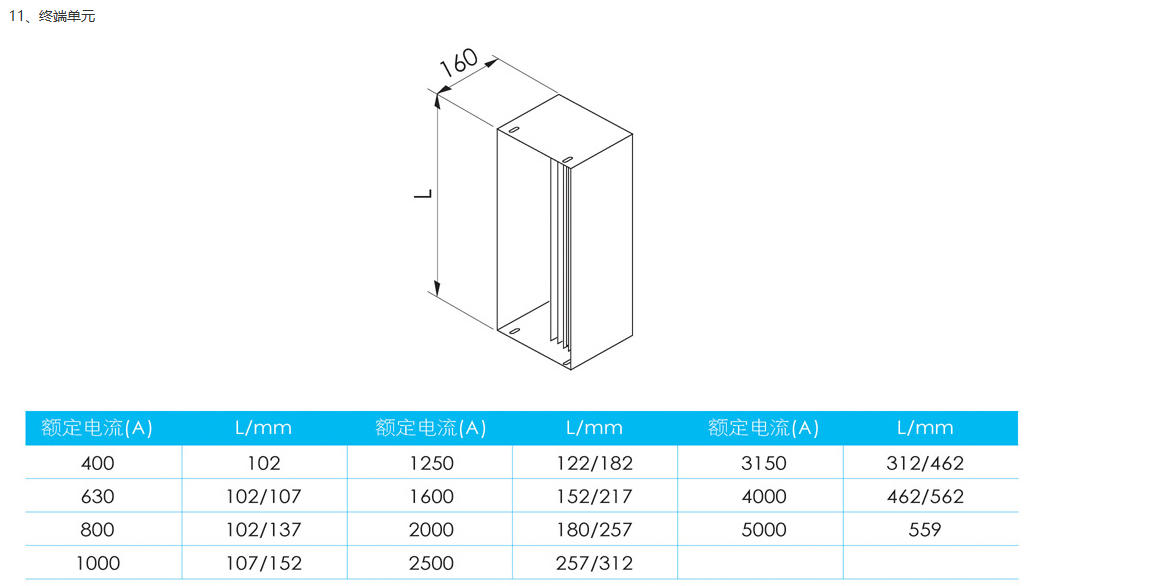
8. Terminal Unit
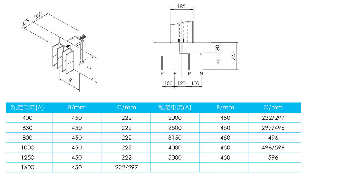
9. Intermediate Input Unit
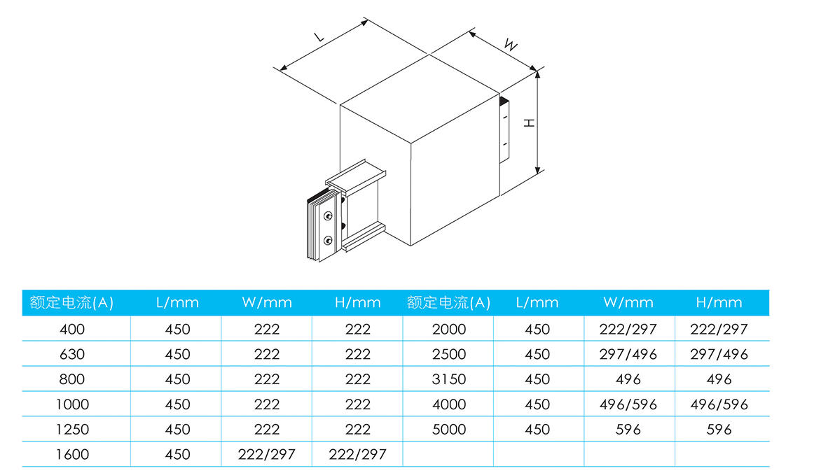
10. Expansion Joint Unit
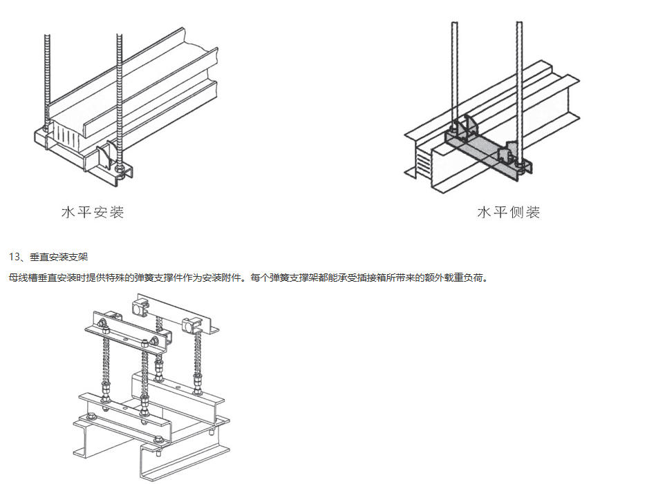
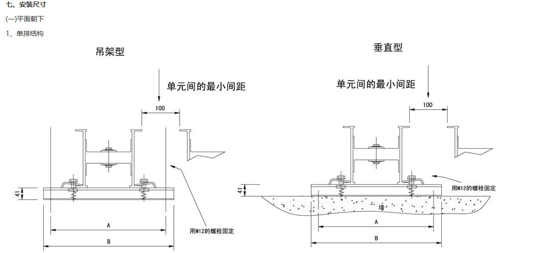
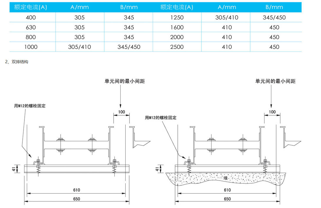
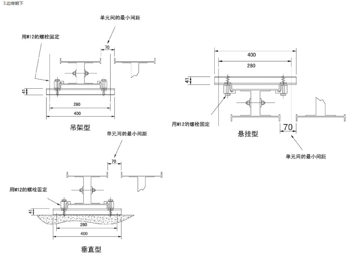
12. Horizontal Mounting Bracket
· The included positioning device on the mounting bracket secures the busway system, making the installed system more stable. Additionally, this positioning device is provided with the mounting bracket.
· Horizontal mounting brackets are available in two types: one for horizontal upright installation and the other for horizontal side installation.
Section 8: Calculation and Selection
1. Rated Current Calculation
When arranging the busbar system layout, the following points should be noted:
· Location, quantity, and connection methods of load or power distribution systems
· Coefficient of dispersion
· Set Short Circuit Level
· Connection to the distribution motor requires: model of the distribution cabinet, incoming line method (top, bottom, or back)
· Installation Location and Conditions: Space dimensions, building structure (for suspension and installation), busway routing environmental conditions (temperature, humidity, air quality, etc.), wall penetration for the system
· Complementary to other systems, such as the installation with busbar systems, includes: the layout of power supply lines, the routing of ventilation pipes, and the layout of the lighting system.
· Please provide the quantity and specific locations of the connector units.
The busbar system is measured strictly according to the points mentioned above, with the first step being to calculate the rated current.

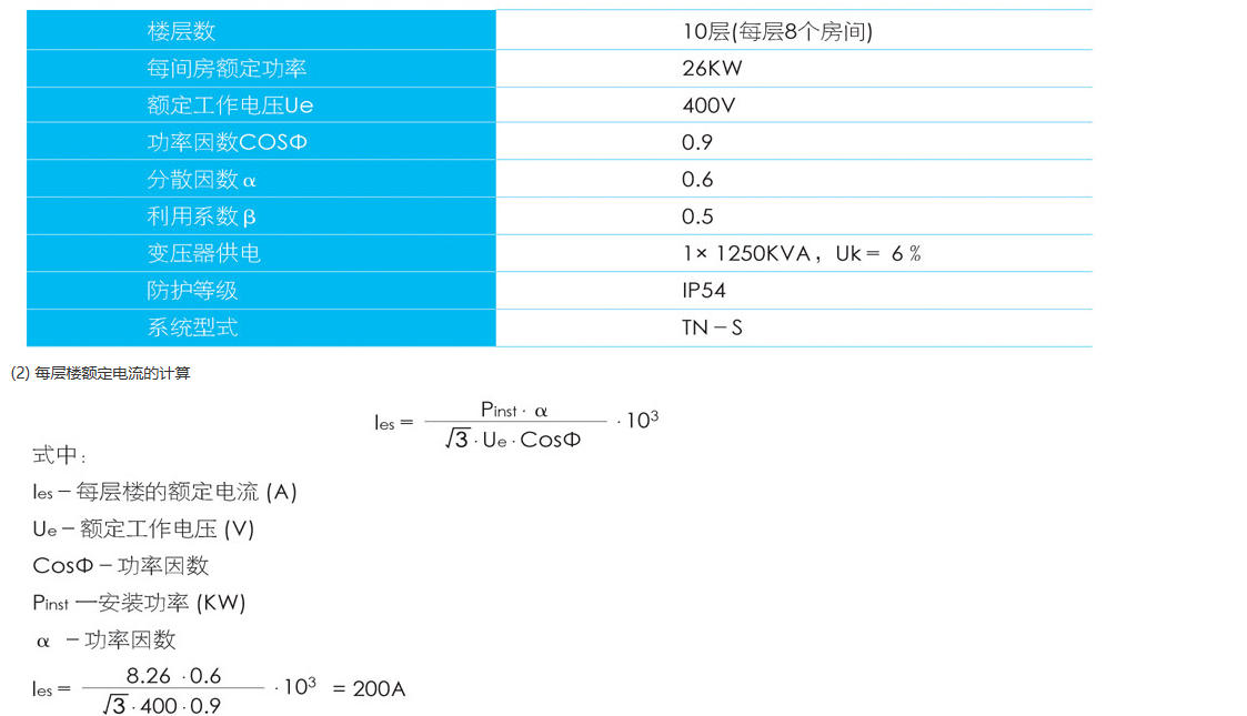
In the formula:
Rated Current (A)
Rated Working Voltage (V)
Power Factor in COS
Pinst - Installation Power
a- Coefficient of dispersion
b- Power Supply Factor
b=1 Single-sided Power Supply
b=0.5 dual-fed and intermediate-fed units
Generally, "a" represents the distributed factor unless otherwise specified; this can be referred to in accordance with the EC/EN60439-1 standard.
Equation
△U Voltage Drop (V)
IB - Rated Current (A)
L-system total length (m)
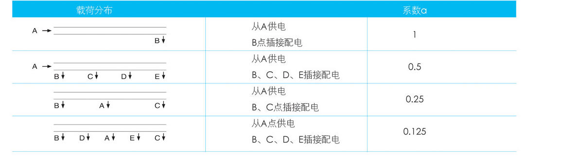
a Load Distribution Coefficient
ROne resistance (mΩ/m)
XOne Reactance (mΩ/m)
Cosφ - Power Factor
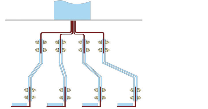
The load distribution coefficient must be determined according to the type of load distribution. The following chart reflects the different methods of load distribution under a constant rated current.
3. Safety disconnection of the minimum single-phase grounding fault current
The return line impedance determines the magnitude of the short-circuit current at one pole, and the conductor for the phase and the protective conductor need to be calculated.
Return loop impedance between the phase conductor and the PEN conductor
The impedance value mainly depends on:
Test Results
Calculation Result
Simulated System
The technical parameters table has detailedly listed the impedance values of the busbar system, thus enabling the calculation of the return line impedance of the busbar system based on these values, leading to the determination of the total return line impedance of the system.
By the return impedance of the entire busbar system, it is easy to estimate the system's minimum short-circuit current at phase 1, or obtain it through calculation.

4. Overload and short-circuit protection
Busbar systems must have overload and short-circuit protection during operation; typically, fuses or circuit breakers are widely used as protective devices within the system. When selecting, factors such as the intensity of the short-circuit current and the operational functions of the system should be considered.
In practical applications, due to the high sensitivity of the fuse, it begins to melt as the current slightly exceeds the rated value, but the melting time is relatively long, making the fuse not very suitable as an overload protection device for use in the system.
If the overload protection device of the busbar槽 system uses a fuse, to ensure the protection device provides suitable protection for the busbar槽 system, the rated current of the fuse must be one grade lower than the rated current of the busbar槽 system.
If a circuit breaker is used for protection, its protection unit can be adjusted according to the rated current of the busbar slot system, meaning the busbar cross system can reach 100% of its load capacity.
If choosing fuses and circuit breakers as protective devices for short-circuit protection of the busbar system, ensure the selected model's current does not exceed the system's protection current. Also, consider factors such as the intensity of the short-circuit current, whether a current-limiting protective device is needed, and the short-circuit switch capacity of the selected protective device.
As follows: I "k ≤ lcc ≤ lcu
Estimated short-circuit current at the installed location
Icc — rated current during system operation
LCU—Rated Short Circuit Current Rating of the Circuit Breaker
5. Case Introduction
(1) Building Power Supply
(3) Calculation of Rated Current for Linear Segments
le=(les x Β)
le=10x200x0.5=1 000A
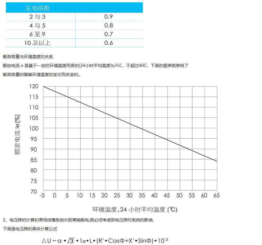
The conversion coefficient is the utilization and distribution coefficient of the total load count. If you're not aware of the specific conversion coefficient, you can consult the local power supply company. They have detailed conversion values for different scenarios.
The following chart lists the average conversion coefficients:

· From the points mentioned above, selecting a busbar system is quite straightforward, for example: a three-phase five-wire system is required, with the neutral line carrying a current of 1250A, and the corresponding short-time withstand current is 50KA.
· Connector Box Unit: The protection current of the connector box unit is 250A, equipped with a three-pole circuit breaker for protection (with an external operating mechanism), a four-wire system, and the connector box unit provides a protection level of IP54.