








Selection and Installation of Cable Trays in Series
I. Scope of Application
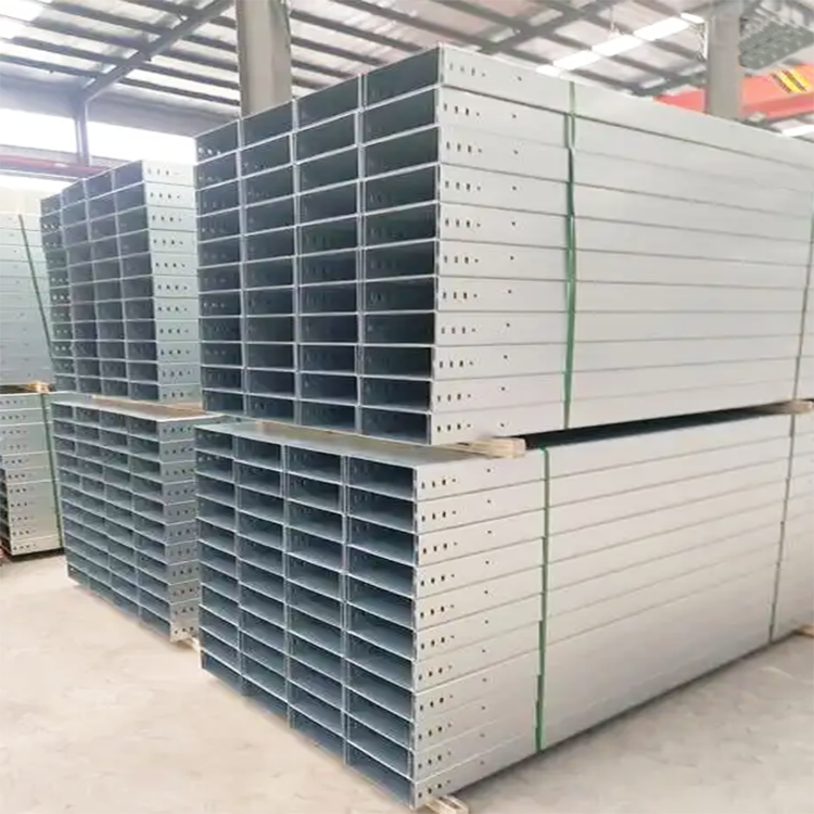
JYQ series cable trays are suitable for power cables with voltages below 10 kV, as well as control cables, lighting wiring, and the installation of overhead cables indoors and outdoors, as well as in trenches and tunnels.
II. Structural Features and Installation
· The JYQ series cable trays feature a wide variety, broad application, high strength, low cost, simple installation, flexible wiring, standard installation, and attractive appearance. They will bring convenience to your technical transformation, cable expansion, and maintenance.
· The installation of the JYQ series cable bridge can be adapted to local conditions. It can be suspended above process pipelines, laid on floors, or installed beneath beams. It can also be mounted on the sides of indoor and outdoor walls, column walls, tunnels, and cable trench walls. When installing on exposed pillars or piers, or for large multi-layer bridge supports, it is recommended to use I-beam pillars with symmetrical installations on both sides.
· JYQ series cable trays can be installed horizontally and vertically: featuring bendable T-shaped branches, cross-shaped branches, adjustable widths and heights, and varying diameters.
Section 3: Cable Layering Arrangement on Cable Trays
The cable tray layering should be arranged with the low-voltage control cables on top, followed by general control cables, low-voltage power cables, and high-voltage power cables in descending order (refer to the table below). This arrangement is conducive to shielding interference, cooling of power cables, and facilitates construction.
The spacing between cable ladder rungs is:
Control Cable: 2200mm; Power Cable: 2300mm; Mechanized Laying Cable: 2400mm.
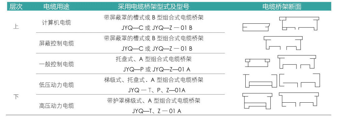
4. Cable Tray Size Selection and Calculation
(1) Calculation of the total load G for cable trays
G General = n1g1 + n2q2 + n3q3 + ...
Equation: q1, q2, q3, etc. represent the weight per unit length of each cable (kg/m).
n1, n2, n3... represent the number of cables.
General G should be less than the allowable load of the cable tray.
When cable trays are installed outdoors or enclosed, factors such as water load and wind load should also be considered.
(II) Calculation of Cable Tray Width b
Calculation of bridge width "b" for power cables:
b = n1(d1 + k1) + n2(d2 + K2) + N3(d3 + k3) + ... where: d1, d2, d3, are the diameters of each cable
n1, n2, n3 are the number of cables corresponding to their respective diameters:
K1, K2, K3 are cable spacing values (k value should not be less than d/4)
2. Calculation of bridge width b for control cables (typically, the filling rate of cable bridges is around 40%):

Section 5: Cable Tray Precautions
1. The load and support spacing for the JYQ series cable tray assembly should be less than the allowable load and support span.
2. When selecting the width of cable bridge, it's advisable to leave some extra space for future cable additions.
3. When there are fewer power cables and control cables, a cable tray can be used for installation, but a partition should be used to separate the power cables and control cables. Place the partition around 1/4 of the span. Fix the horizontally routed cables approximately every 2 meters, and the vertically routed cables approximately every 1.5 meters.
4. Cable tray installations should have a reliable grounding. If using the tray as the grounding main, connect the ends of each tray layer with 16mm² soft copper wire (in parallel) to the main grounding trunk. For long-distance cable trays, ground every 30 to 50 meters.
5. Cable tray assemblies, in addition to requiring shielding protection, should be fitted with a protective cover on the top when installed outdoors to prevent sun exposure and rain. If welding installation is required, the weld bead thickness around the weldment must not be less than the thickness of the base material, and the weld joints must be treated for corrosion resistance.