






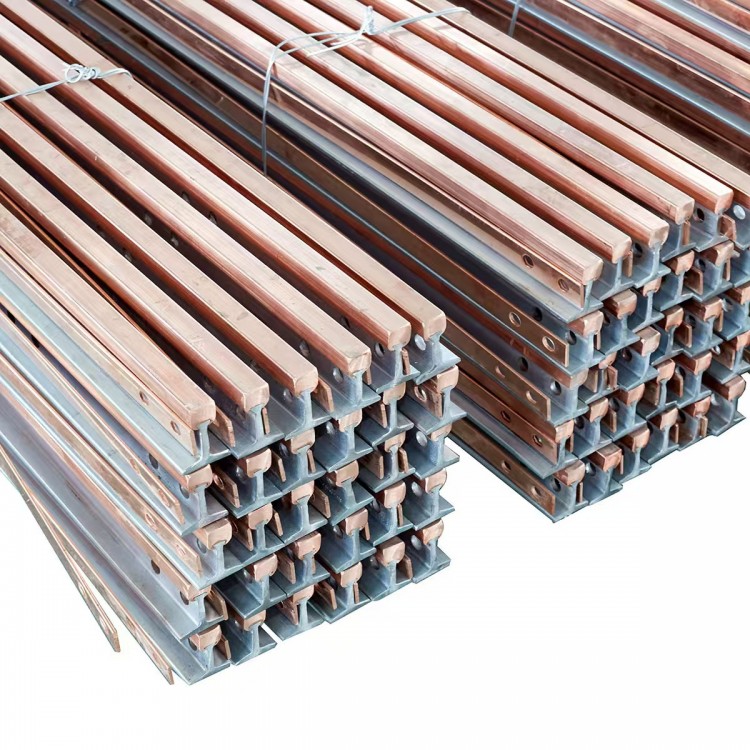
Product Overview
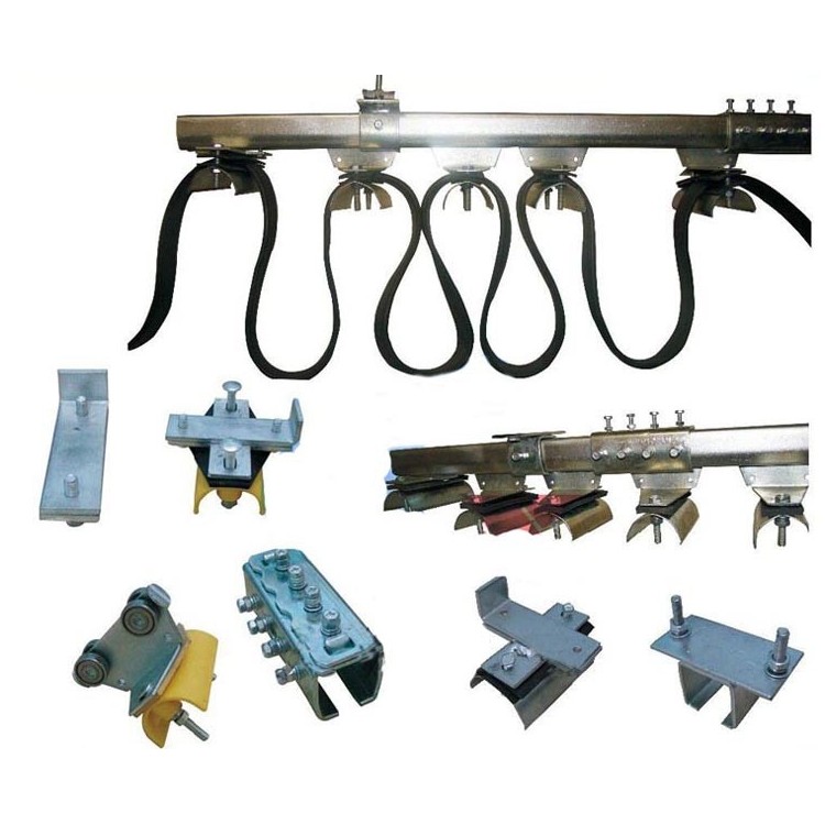
The JYC series cable slider system consists of tracks, cable carriers, round or flat soft cables, suspension brackets, fixed accessories, etc. This product, with its simple and comprehensive performance, is widely used in metallurgy and steel, petrochemical industries, railway cargo yards, ports, tobacco machinery, water supply, and environmental protection systems requiring mobile power supply.
Due to the flexible configuration of the system, by setting up corresponding straight line segments, curved segments, and switch conversion devices, it can form production process hanging lines for various uses. At this point, it not only serves as a mobile power supply but also carries water, gas, oil pipes, and other suspended loads, excluding cables. It is currently widely used in assembly and workpiece transfer systems in industries such as vehicle manufacturing, mechanical and electronic, and light industry.
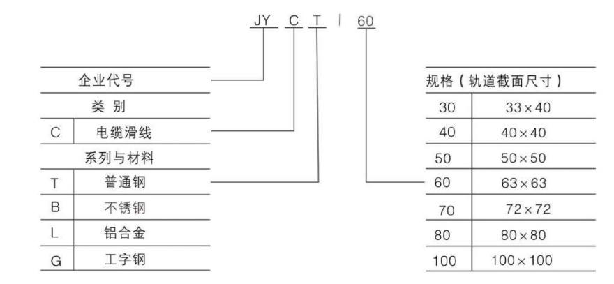
Product Model and Its Meaning
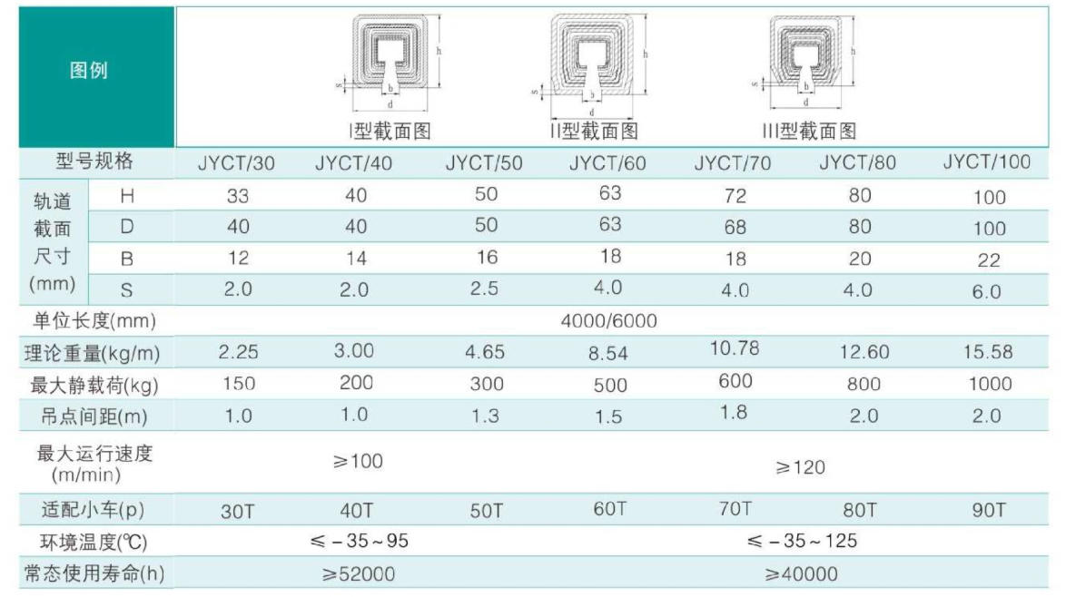
Key Technical Data
Working Principle and System Composition
(1) Working Principle
This product is composed of three main parts: flat cables, four-wheeled trolleys for carrying cables, and guide rails. The guide rails are made from cold-rolled steel plates, cold drawn into shape in one process to ensure precise cross-sectional dimensions. This replaces the unsafe, heavy, and dusty drawbacks of angle iron and other conductive methods, as well as the risk of short circuits caused by outdoor icing. It boasts unique domestic features, with guide rail lengths of 4 to 6 meters, connected by joints that can be extended to any desired length as needed.
Flat cables are made of non-flammable materials, suitable for both indoor and outdoor use, and for contact with oil污. They offer certain climate resistance and have advantages over round cables, such as smaller bending radius and longer lifespan. The working principle of this product is illustrated in the following diagram. The starting end of the flat cable (connected to the site junction box) is fixed to the starting fixture of the guide rail. Then, according to the allowed operating space on-site, it is fixed at appropriate intervals (1~2.5m) on a trolley carrying the cable. The cable end (connected to the power source) is fixed to a small trolley on the traction vehicle, which is moved back and forth through the spring mechanism on the trolley. The movement is driven by the cable's pull (consider using the original牵引绳 if the length exceeds 20m to prevent tension on the cable). This allows all trolleys to move freely at any speed along the track. The guide rail is easy to install, requires no adjustment, and offers contactless power supply, making it safe and reliable.
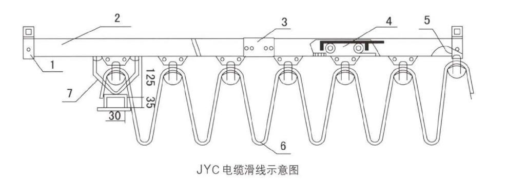
1. Hanger 2. Track 3. Coupling Joint 4. Trolley 5. End Stop 6. Flat Cable 7. Tugger
Description: 1. Track sizes available in 4m or 6m lengths; for single lines exceeding 6m, couplings can be fitted at the joints.
2. Guide rail hanging point spacing is 2-2.5 meters, meaning one top suspension bracket is set every 2-2.5 meters.
(System Composition)
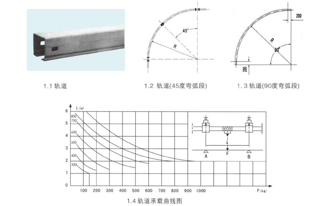
1. Tracks serve as the carrier for cable vehicles, consisting of straight sections and curved sections to form any type of aerial transmission line. Due to the availability of materials such as aluminum alloy, common steel, stainless steel, and I-beams, users can select different tracks and cross-sections based on varying usage environments and loads. The standard length of the straight sections of the track is either 4 meters or 6 meters, while the curved sections are customized according to customer requirements with different bending radii and angles, with a standard bending radius of 1000 millimeters.
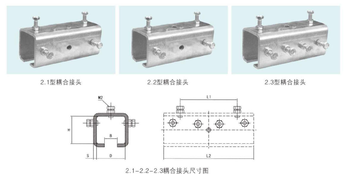
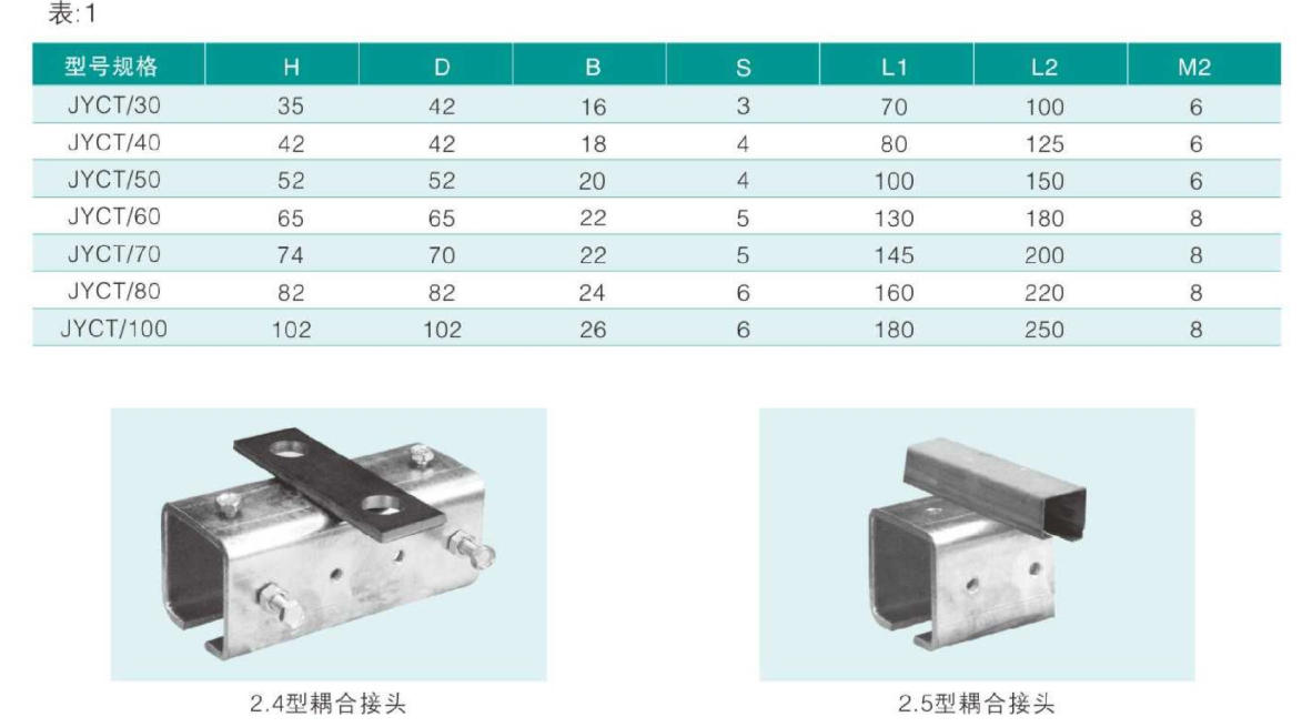
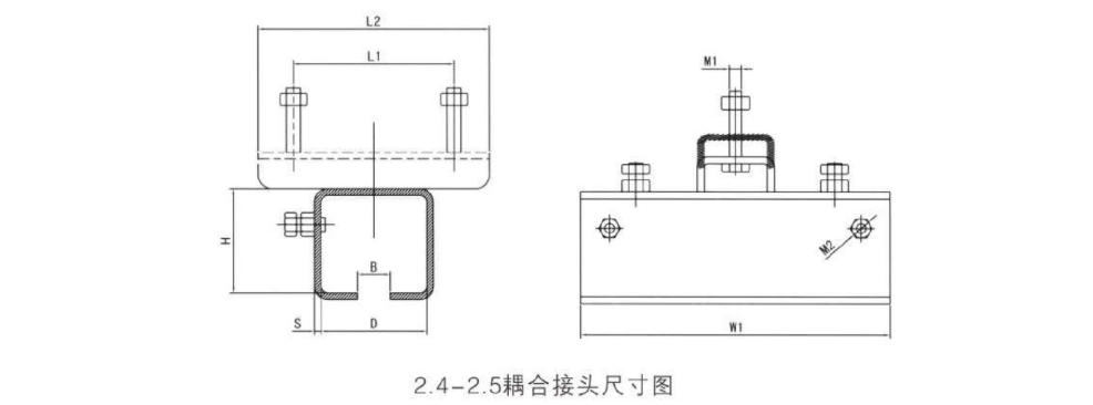
2. Coupling Joints - Coupling joints are essential components for connecting tracks, composed of a C-shaped sleeve made from the same material as the track body and corresponding fastening hardware. By adjusting the fastening hardware, the connection between tracks can be made secure and the transition smooth, ultimately achieving the purpose of extending the track indefinitely.
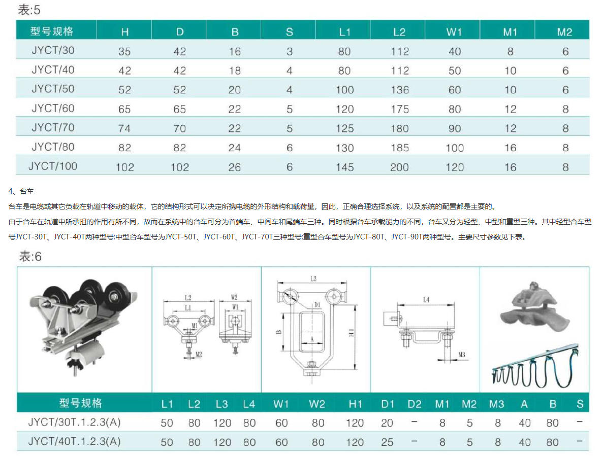
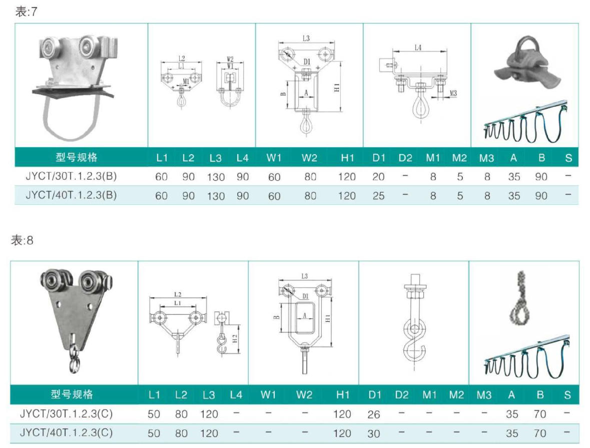
4.1 Leading Trolley: The leading trolley is the tow vehicle for the cable carrier, propelling the trailing trolley through its drive mechanism. It features four fully enclosed rolling bearings as its running wheels, offering exceptional smooth movement and suitable for dusty and harsh environments without the need for lubrication.
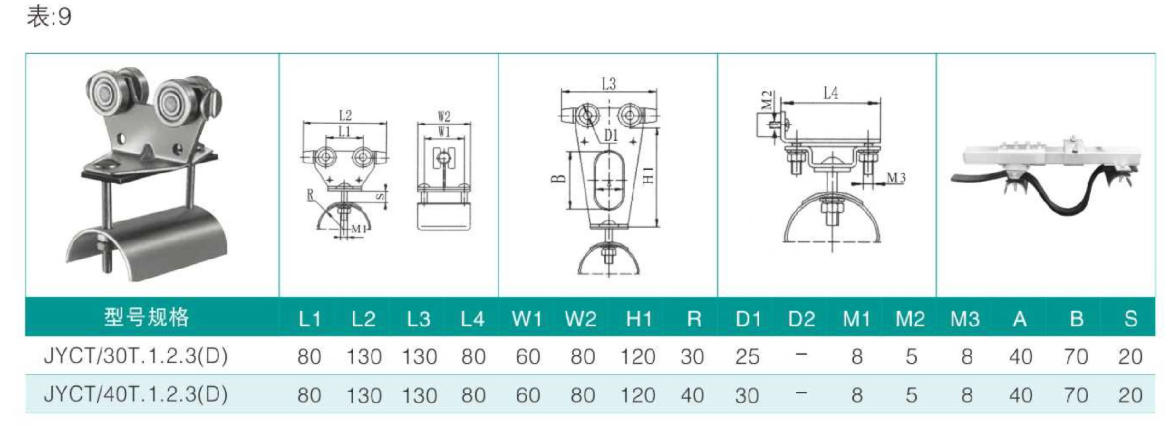
4.2 Intermediate trolley
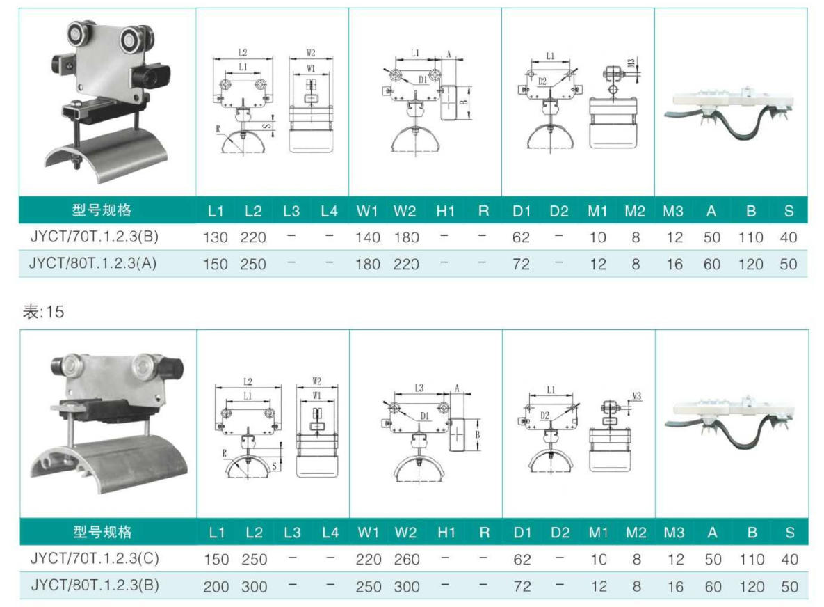
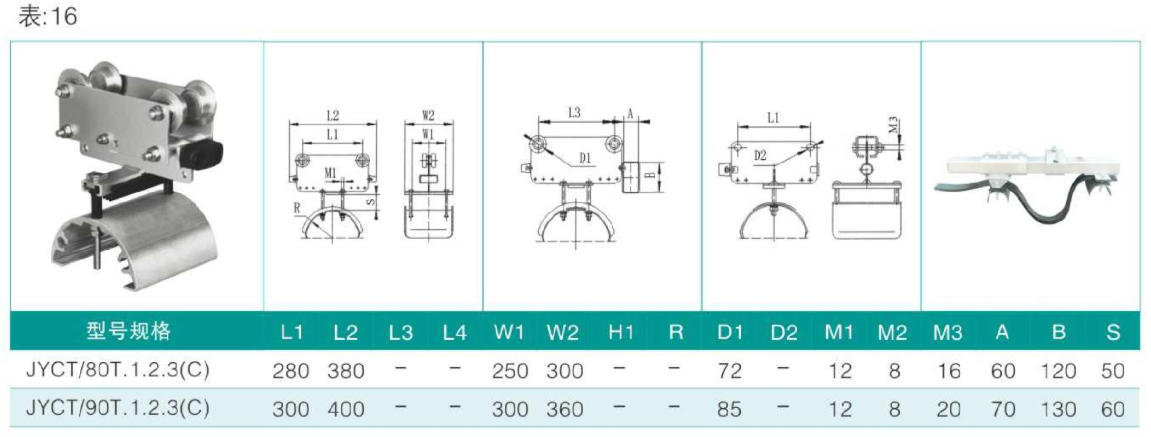
The intermediate cable carrier is a tool for supporting cables or other loads, which slides automatically under the action of external force, with its rolling wheels featuring fully enclosed rolling bearings. The curved bracket for lifting and hanging cables is equipped with a soft rubber thermal layer to protect the cables or other flexible hoses. The middle flexible steel wire rope (chain) directly pulls between each cable carrier to ensure that the cables are not damaged by direct tension. Both the first car and the intermediate cable carriers are equipped with collision shock absorbers to ensure that there is no direct impact between the carriers due to movement forces.
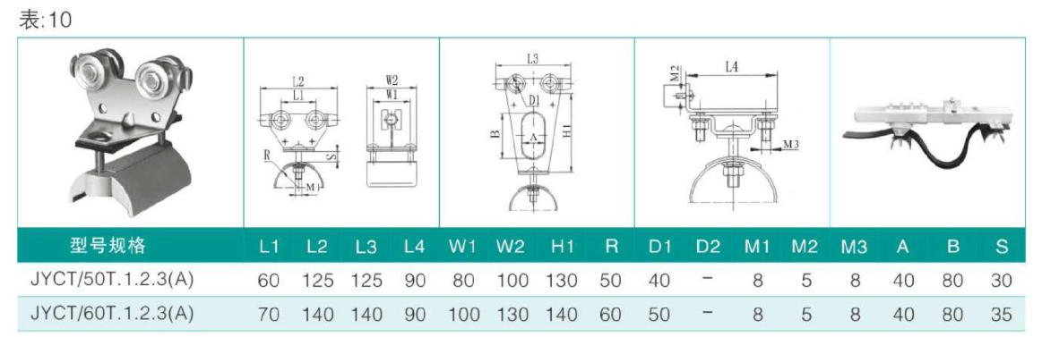
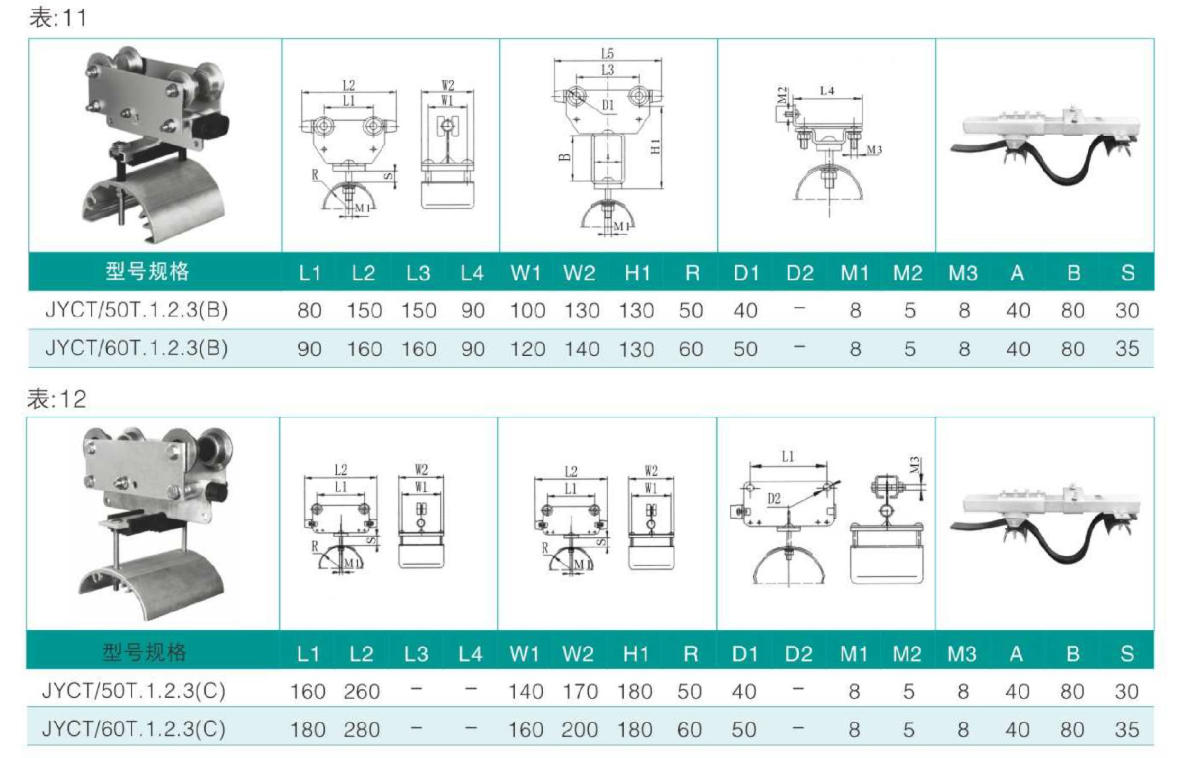
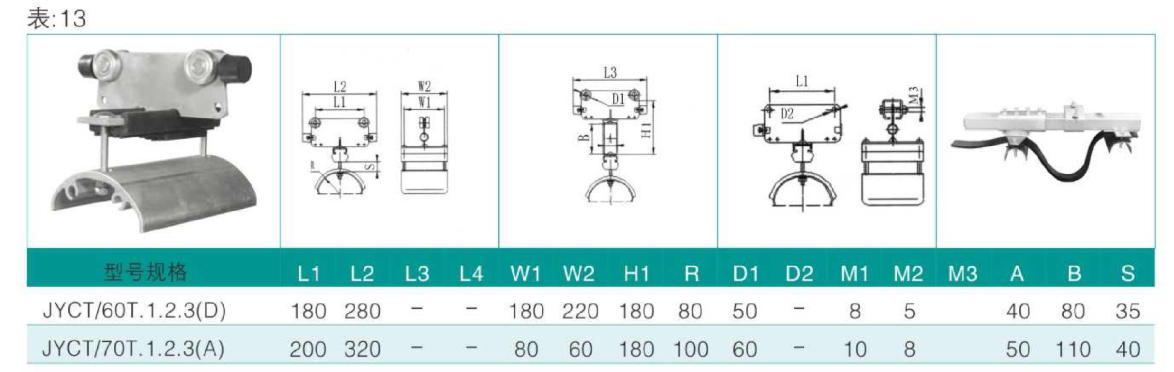
4.3 The end carriage with cable carrier is a stationary load tool for fixed cables or other loads; it has no moving function, thus no rolling wheels. The curved support for the cable hoisting part is equipped with soft rubber pads to protect the cables or other flexible hoses. The cable carrier is directly connected to the end carriage with a flexible steel wire rope (chain) to ensure that the cables are not damaged by direct tension. The end carriage must be securely fixed to prevent derailment.
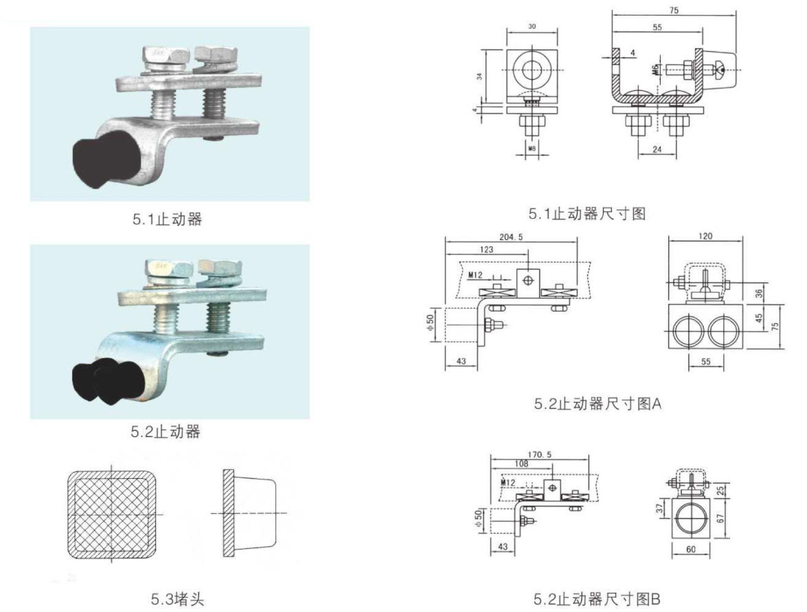
5. Locking Device
The stopper is a safety device at both ends of the track. Due to its varying functions and requirements, its appearance and structural form are not uniform. Users should pay attention to selection when choosing one.
Available for selection and configuration to meet different requirements.
6. Traction unit
The trailer is a transition component between the system's mobile devices and the cable carrier (the lead vehicle). Due to the different traction methods of various mobile devices, the trailer types also vary. Generally, they can be categorized into two types: rigid direct traction and flexible indirect traction. Users can select and configure according to different requirements.