

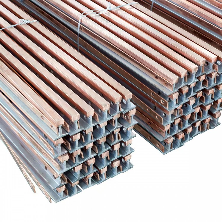


The JYG series rigid sliding busbars are composed of guide rails, connecting components, expansion components, insulating components, fixing components, support components, and collector components. Due to their features such as high current carrying capacity, low power loss, excellent tensile strength, reliable operation, and easy maintenance, these products are widely used in harsh environments like high temperatures, high humidity, dust, and strong corrosive gases. Consequently, they are extensively utilized in industries such as steel metallurgy and shipbuilding at ports.
Product Features
Operation is reliable and less prone to power interruption failures; suitable for harsh environments such as high temperatures, high dust, and high corrosion. After adopting the dovetail groove mounting process, it resolves the issue of screw loosening caused by vibration during the operation of other rigid conductive wires, thereby ensuring the integrity of the sliding wire assembly.
Body robust and reliable;
High mechanical strength, resistant to bending and deformation, capable of withstanding powerful short-circuit surge currents; current-carrying capacity can be set according to user requirements, exceeding 1800 mm², and voltage levels can reach up to 6kV; copper conductor for electrical conduction, significantly reducing wire energy loss. With the addition of auxiliary cables, it can form a low-impedance sliding contact line, reducing line impedance.
Large heat dissipation area, compact and simple structure, easy installation and maintenance.
Cabling can be slided either from the top or the side: the collector uses a torsion spring for even pressure, with bipolar brushes: it has excellent electrical continuity capability.
In practical use, side slides are more stable and rational than top slides. Their advantages include a significantly increased lifespan for the collector and an extended brush life by 3 to 4 times. Cable retention clips are also employed.
Specification Model
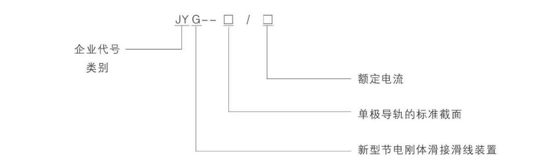
1. The specifications of the rigid slider line are determined by the nominal cross-section of the copper rod.
2. The models, specifications, and rated current values of the rigid sliding contact lines are as listed in the table below.
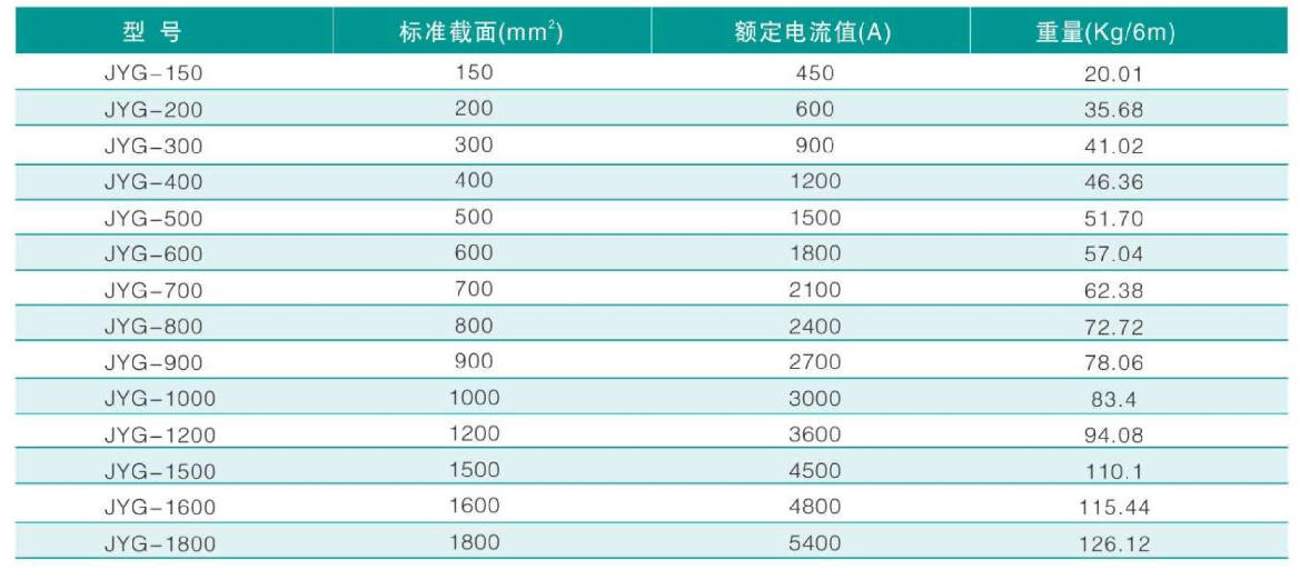
Generally, rigid slider cables are supplied in fixed lengths of 6 meters: the spacing for the rigid slider cable brackets is typically 3 meters.
Product Model and Its Meaning
Series component code for rigid slider line:
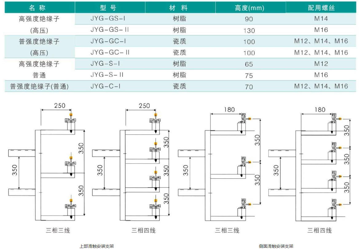
Insulator with Fixed Mounting (or Insulator Assembly)
K-Clamping plate for K-type sliding contact wire fixation
Steel core for G-type sliding contact bracket connection
F-Supply Terminal
E-Inspection and Isolation Terminal Device
L-Accessory Cable Clamp
Temperature Compensation Device
D-Collector
Product Structure
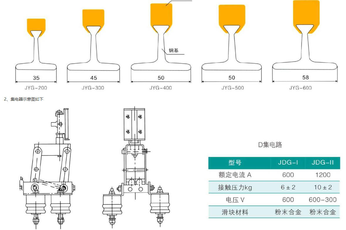
1. The cross-sectional view is as follows:
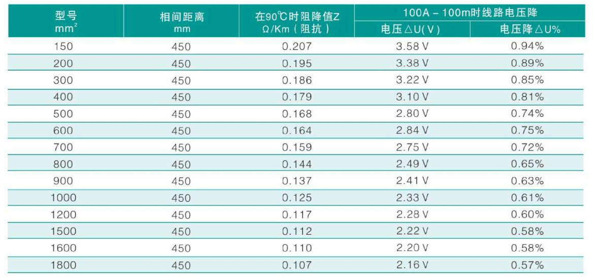
Technical Specifications
Conductor impedance and voltage drop at 100A-100m (using 380V, with a power factor of 0.8)
Load Current Calculation
1. Load Current Calculation
The calculation method for the load current of sliding contact lines, previously used the binomial formula. Now, we introduce the calculation method commonly adopted in foreign literature, which is as follows: multiply the rated current of the motors that may operate simultaneously on the crane by the temporary load factor and the simultaneous operation coefficient of multiple cranes. Load Current (I) = Total Rated Current of Operating Motors (IH) x Temporary Load Factor (FED) x Simultaneous Operation Coefficient (F)
FED temporary load factor is determined as per the table below
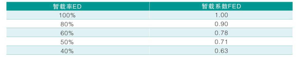
Multiple cranes working simultaneously: Coefficient F ranges from 0.4 to 0.7.
2. In the past, when designing sliding contact lines, high current was used to test voltage drop. This means that the voltage drop from the feeder switch on the low-voltage panel (from the secondary side of the transformer to the end of the sliding contact line, including the supply cable) should not exceed 12%. In other words, the sliding contact line and the supply line are considered as a whole, and efforts should be made to minimize investment while meeting the voltage drop requirements. With the increase in projects in recent years, and based on comprehensive foreign data, it is generally accepted abroad that voltage drop should be tested using calculated load current, including the supply line, with the voltage drop to the end of the sliding contact line not to exceed 5%.
Voltage Drop Calculation Formula:
AU=V3xlx1xz or AU=V3xlx1x(RCos+XSin)
In the formula: △U = Voltage Drop l = Calculated Load Current R = Resistance (Ω/Km)
X Inductance (Q/Km) Z Impedance (Q/Km) L Contact Line Calculated Length (m)
Sliding contact wire calculation method: Let L represent the total length of the sliding contact wire (m)
When powering at the end of the busbar: l = L, When powering at both ends of the busbar simultaneously: I = L/4
When powering at the center of the busbar: l = L/2 When powering at the ends of the busbar at L/6: I = L/6
Installation method, main components, and rigid busbar connection
The installation method of sliding contacts typically includes overhead and side sliding types, which can also be customized according to the customer's requirements.
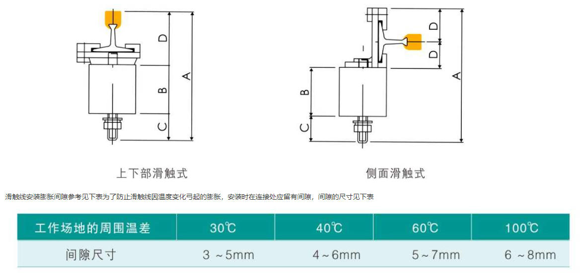
The dimensions with reserved gaps are related to the installation environment temperature; generally, use higher values during winter installations and lower values during summer installations.