Centrifuge, Chromatography Systems, Ultrafiltration Equipment, Fermenter Technology Development
13818500291
This machine boasts excellent anti-interference capabilities; stable operation and normal functioning can only be achieved by accurate installation as per instructions and strict operation.
3.1 Machine Installation
Do not connect the motor to the drum with a belt unless the machine is fully assembled.
3.1.1 The installation site must be located away from heavy machinery or impact equipment such as punches, shears, and forgers to avoid vibration and interference.
3.1.2 The machine is fixed on a concrete foundation, constructed according to the foundation drawing provided by the manufacturer. The installation location should ensure that there is a 1.5-meter clearance in front of and on both sides of the machine, with adequate space at the top for ease of maintenance and hoisting.
3.1.3 When transporting or lifting, the drum must first be removed. Be cautious to prevent damage to machine parts. There are lifting holes above the machine, and the force point should not be on the head, belt wheel, motor, handle, etc.
3.1.4 For on-site installation, the internal parts must be properly protected to prevent damage during transportation and lifting.
3.1.5 During the installation of the fuselage, the horizontal alignment must be checked at the flat surface of the fuselage mounting head. The unevenness in the two vertical directions should not exceed 0.06mm/m to prevent uneven wear on the bearing.
3.1.6 The motor must be vertically mounted, with the main belt pulley horizontally aligned at the same level. The flatness of the main belt pulley should not exceed 0.10mm/m.
3.1.7 The steering of the separator is clockwise when viewed from above (indicated by an arrow). The crank of the belt pulley is allowed to rotate counterclockwise only when viewed from above, with an angle not exceeding 360°.
3.1.8 The machine's power specifications and power wiring must comply with the label specifications.
3.2 Assembly of Parts
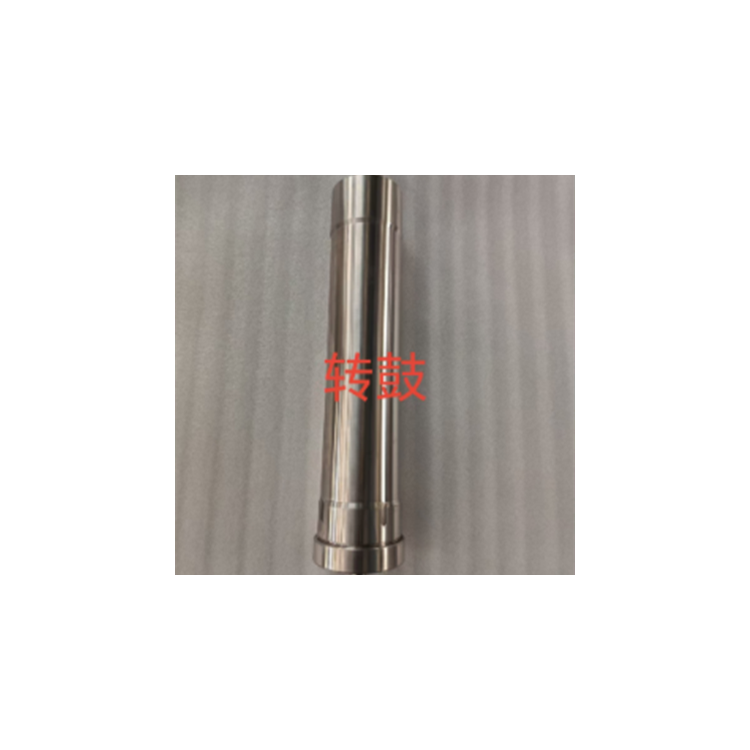
3.2.1 Drum Assembly
The centrifuge drum is a critical component, which must be protected and maintained as meticulously as precision instruments.
The drum is a critical component of the centrifuge, and it is essential to carefully inspect the inner and outer walls, mating surfaces, sealing surfaces, and threads during disassembly; check for any damage, foreign objects inside the drum, and the cleanliness of the inner and outer surfaces.
Upon separation of the drum from the main shaft, the upper thread must be fitted with a protective sleeve. The protective sleeve must not be removed unless the main shaft is properly engaged and secured with the connecting nut.
3.2.1.3 Place the drum horizontally on a dedicated bracket, ensuring the pins on the bracket fit into the corresponding slots on the bottom of the drum. If a trapezoidal plate is installed inside the drum, it must be cleaned and pushed into the drum parallel to the designated marks until it reaches the top.
3.2.1.4 When using a trapezoidal prism, check if the steel wire is loose, if the prism is deformed, or if there are burrs. If using a quadrangular prism, inspect if the prism is loose or deformed.
3.2.1.5 Inspect the bottom cover, checking the seal ring, mating surface of the bottom, and threads for cleanliness and integrity. The bottom cover's head gasket must not be loose or excessively worn, and replacement requires tools. When dismantling, the clamp should not be too tight to avoid damaging the threads.
3.2.1.6 Use a梅花 wrench and a wooden hammer to tighten the bottom cover onto the drum until the specified marks align. The allowable deviation between the drum marking and the cover marking is ±10mm (arc length). If exceeded, check the cause. If there is an issue with the sealing ring, replace it with a new one.
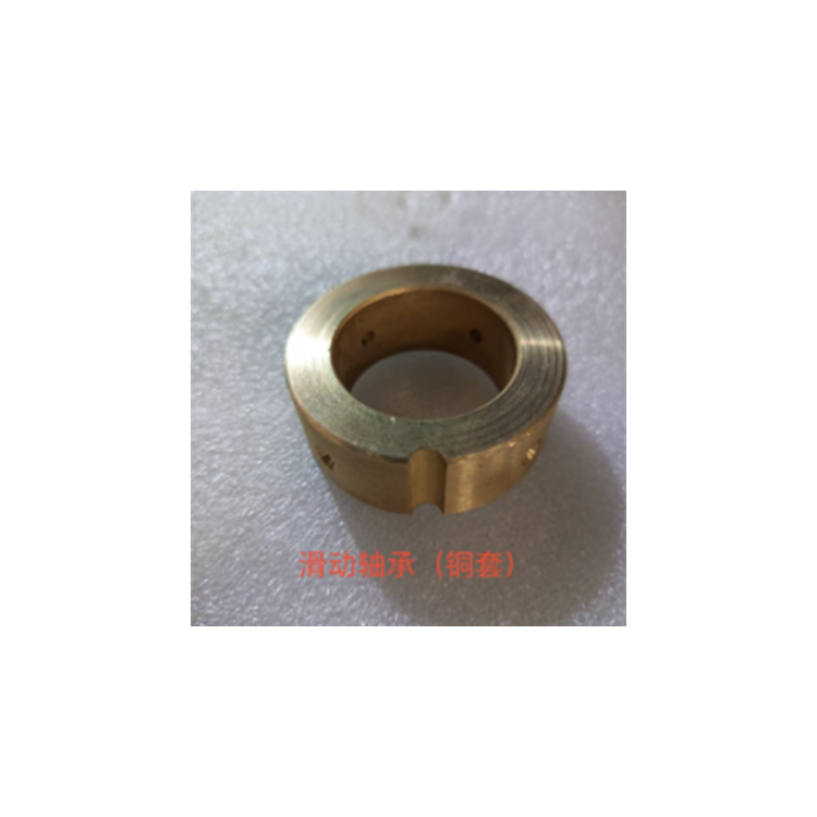
3.2.2 Lower bearing assembly
Radial sliding bearings must allow for flexible movement, and the cleanliness and lubrication of the grease must be ensured.
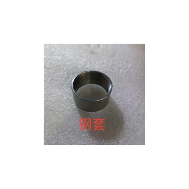
Ensure that the bearing sleeve and bearing housing contact surfaces are flat and that the sliding bearings are not excessively worn. If the wear exceeds 0.8-1mm, replace the sliding bearings.
Ensure smooth oil pathways; use No. 2 lithium-based grease; the oil cup and grease must be clean and of normal color.
3.2.2.3 During the installation of the sliding bearing, align the slot with the locating pin of the bearing sleeve. Push it in by hand, then tighten the bolt with M8 threading on the bearing sleeve securely, without any looseness. Finally, tighten the sliding bearing cover.
3.2.2.4 Apply lubricant to the worn surface of the assembled bearing at the bottom and the worn surface on the bearing housing. Align the pin into the radial slot of the bearing housing, then place the compression spring on top.
3.2.2.5 Secure the bearing housing to the vise, screw the outer cover into the bearing housing clockwise, and tighten it with a crescent wrench.
3.2.2.6 Check the radial movement of the sliding bearing for smoothness and even force application. Confirm normal operation, then place the sliding bearing in the center position as observed.
3.2.2.7 Rotate the oil cup lid to allow the grease to enter and exit through the hole in the sliding bearing.
Apply a small amount of lubricating grease to the sliding bearing working surface and keep it clean.
Contact us

Service Hotline
13818500291
Company Telephone
13818500291

Address
999 Jiangyue Road, Building 1, Room 111, Minhang District, Shanghai
www.114global.com © Zhongshang 114 Hebei Network Technology Co., Ltd.Address: Room 6009, Oriental New World Center, No.118 East Zhongshan Road, Qiaoxi District, Shijiazhuang City, Hebei ProvincePlatform Service Hotline: 4006299930