


To ensure the stable operation and normal functioning of the high-speed tube separator, please fulfill the responsibilities listed in the table below during maintenance and care.
4.1Maintenance and Care Responsibilities
| Responsibilities | 规定时间或程度 - Specified time or extent | Purpose |
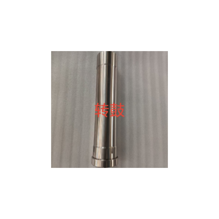
| The top thread of the drum is secured with a protective sleeve. | Prior to the drum being connected to the main shaft. | Prevent collision damage to threads. |
| 2. Drum cleaning and disinfection. | Following each centrifuge shutdown. | Eliminate solid residues, maintain balance. |
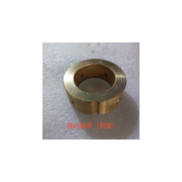
| 3. Clean and inspect the bearing assembly. | Once a week or more frequently, depending on usage. | Remove debris, inspect flat wear, ensure bearing seat smooth contact. |
| 4. Replace the lower bearing spring. | Once a year. | Ensure effective damping performance. |
| 5. Lubricate sliding bearings. | Add a moderate amount of oil before each startup. | Ensure damping effect and bearing lubrication. |
| 6. Replace sliding bearings. | When worn to a diameter of ≥ φ36.4mm. | Ensure smooth operation and prevent feed tube abrasion. |
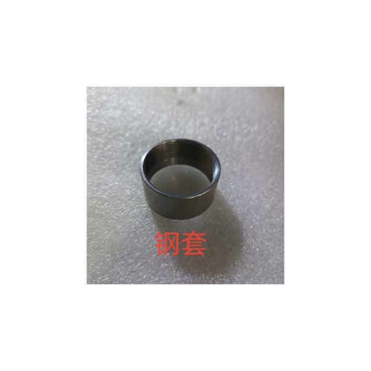
| 7. Replace the bottom cover gasket. | When the diameter wear reaches 0.5mm or the scratch depth on the outer surface exceeds 0.2mm. | Ensure smooth operation and prevent wear on the threaded connection between the bottom cover and the liner ring. |
| 8. Replace the belt. | When the belt exhibits fabric wear. | Avoid belt breakage. |
| 9. Inspect the belt alignment on the belt pulley. | When the centrifuge is started or when the belt is unevenly loaded on top and bottom. | Prevent damage from belt unilateral wear. |
| 10. Replace drum seal. | When the seal ring is damaged or misaligned with the drum balance marks by more than ±10mm. | Ensure sealing performance and drum balance. |
| 11. Cross-Selling Swap | When the single-sided wear exceeds 0.1mm. | Maintain neutral accuracy in coordination. |
| 12. Replace the main shaft. | When the end face of the shaft fits are damaged or the shaft is out of round by more than 0.03mm. | Ensure smooth operation. |
| 13. Cleaning and lubricating the pressure roller bearing. | Refuel monthly and clean after a cumulative operation of 1,000 hours. | Ensure lubrication and low noise. |
| 14. Replace the tension roller bearing. | Every 1,000 to 2,000 hours or when the noise is loud. | Ensure smooth operation with low noise. |
| 15. Replace the tension spring for the pressure roller. | Once a year. | Ensure proper belt tension. |
| 16. Engine Head Bearing Cleaning and Lubrication | Once a week, add a moderate amount of oil; clean once a year. | Ensure lubrication and low noise. |
| 17. Replace engine head bearing. | Every 1000 hours or when the noise level is louder. | Ensure smooth operation and low noise in machinery. |
| Check the contact degree between the sliding bearing sleeve and the bearing housing. | Surface spots must be in contact, with a contact area of ≥40%, typically checked during routine annual inspections. | Ensure damping effect. |
| 19. lubrication or replacement of motor bearings. | Annual inspections are typically conducted or depend on usage. | Ensure the motor operates smoothly. |
| Inspect motors, switches, starters, and other electrical equipment. | Routine annual inspections are conducted. | Ensure safe operation of motors. |
| 21. Inspect the motor and main pulley for vibration and balance. | Routine inspections are conducted during annual maintenance, and also depend on usage. | Ensure smooth machine operation with low noise. |
| 22. Calibration of machine level. | Routine inspections are conducted during the annual check-up. | Ensure compliance with the specified waviness requirements. |
| 23. Drum damage conditions and safety inspections. | Annual inspections are typically conducted, and also depend on usage. | Ensure smooth operation with low noise and safety. |
| 24. Drum balancing inspection and correction. | Routine inspections are conducted annually, and also depend on usage. | Ensure smooth operation, low noise, and safety in machine running. |
4.2 Maintenance of main components
4.2.1 Drum Conversion
4.2.1.1 Overview
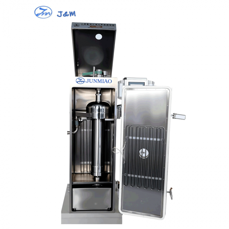
The drum is a core component of the tubular centrifuge, essentially a cylinder with a removable but non-detachable top cover for drainage, a removable bottom cover for discharging and cleaning purposes. There is a sealing ring between the bottom cover and the cylinder, and the interior of the drum features three-sided or four-sided plates.
The top thread and the flange on the drum are used for connecting the nut to the main shaft and for positioning the drum. To ensure the coaxial alignment after the main shaft and drum are connected, please protect the thread and flange at all costs.
If installing the three-leaf plate, its relative position to the drum is fixed to ensure balance. There is a mark on one edge that must be aligned with the mark on the cylinder and pushed into the cylinder until it is fully seated.
If it is a tetrahedral plate, be careful not to loosen the plate during assembly and disassembly; its connecting thread is left-handed.
The drum is carefully balanced, and the bottom cover with a qualified sealant installed is tightened to the drum body, thereby establishing the reference mark. Due to minor variations in the gasket thickness, slight misalignment may occur between the bottom cover and the drum body's mark during tightening, but it should not exceed 10mm. Generally, it is required to be within ±10mm. Any deviation beyond this should prompt a replacement of the sealant.
The bottom cover head features a replaceable gasket ring. When the drum operates beyond the critical point or with a slight increase in amplitude, the gasket ring comes into sliding contact with the sliding bearing. Therefore, the surface must be smooth with appropriate hardness and wear resistance. Any scratches on the surface should be polished with sandpaper. If the diameter wears down to 0.5mm or the scratch depth reaches 0.2mm, it should be replaced. Excessive wear can damage the fine threaded groove on the bottom cover.
The cylinder and bottom cover are mated surfaces connected with trapezoidal threads. Due to both being made of stainless steel, they are prone to locking. If disassembly is permitted, a special lubricant can be applied before each assembly. In case of locking, it is necessary to have a professional perform some scraping and grinding, or have the machine manufacturer repair it.
Improper bearing clearance or excessive machine vibration can cause the lower cover feeding position to rub against the feeding nozzle. The cause should be identified and prevented. Any friction damage should be smoothed out promptly. If the damage depth exceeds 0.8mm, it should be referred to the machine manufacturer for a safety inspection.
Note:Ensure the protection of the separation筒 body sealing end face. During the operation of the centrifuge, the drum wall withstands great pressure. If the lower end cover is not sealed properly, a leak can occur, causing the material's liquid to be ejected at high speed. This can lead to metal wear on the sealing end face, making it inevitable that leakage will occur even if the lower end cover is tightened during the next installation.
If the drum is not used for a long time, it should be removed, thoroughly cleaned, and properly stored. A thorough inspection must be conducted before the next use, and it should not be used if it does not meet the requirements.
4.2.1.2 Disassembly
Using specialized wrenches, secure the main shaft connection nut and the flat slot on the drum head. Apply an impact torque (right-hand thread) to unscrew the nut, remove the main shaft, and push the main shaft upwards towards a tighter position on the machine head.
Thread the protective sleeve onto the drum's top.
The drum must be placed on a dedicated bracket, and only after proper alignment can it be disassembled.
The bottom cover is connected to the cylinder with a right-hand threaded joint, requiring a special bottom cover spanner to remove or install the bottom cover. Pay attention to the correct position of the spanner to prevent deformation of the bottom cover's semi-circular hole.
Pull a hook to pull out a trapezoid.
When removing solids adhering to the drum wall with a tool, be cautious not to apply force against the drum body wall's end with the metal tool.
When removing the bottom cover gasket, the bottom cover should be secured on a specialized fixture or directly tightened onto the cylinder, then removed using a specialized steel sleeve wrench. The threads are right-hand threads; the wrench should be tightened appropriately, as over-tightening may damage the bottom cover threads.
All hammering during disassembly must be done with a soft hammer; metal hammers are prohibited.
4.2.1.3 Cleaning
Cleaning can be conducted according to the requirements of the separation process.
Do not use media that corrodes stainless steel during cleaning. Ensure the seal ring maintains its operational performance after cleaning.
The washing and drying temperature must not exceed 100°C, and the lower cover's sealing ring must not exceed the temperature specified by the material. Drying must be done using an oven; direct roasting with open flame or high-temperature heat sources is prohibited.
After cleaning, ensure that all parts of the drum (including threads, small holes, etc.) do not have any visible residue or dirt, as excessive residue can affect the drum's balance.
The cleaning tools used must not damage the drum components.
Ensure that parts are handled carefully during washing and drying to avoid磕碰, and use designated tools for storage and placement.
4.2.1.4 Assembly
Inspections and measurements of drum components should be conducted during or after cleaning, and any damage should be repaired or replaced promptly; repair operations must be performed by trained professionals.
Position the drum correctly on the dedicated rack.
Insert the qualified sealing rings into the bottom cover, ensuring they are even and flat.
Apply a small amount of special lubricant or lubricant allowed by the disassembly process to the thread area where the lower cover and the rotating cylinder fit, then screw the lower cover onto the rotating cylinder until tight, aligning with the mark. The tightness of the mark must ensure an accuracy within 10mm.
Apply a small amount of lubricating oil to the mating surface of the bottom cover and sleeve. Securely tighten with a steel socket wrench, then inspect the surface finish; if rough, it should be polished.
Drum cleaning and proper storage.
4.2.2 Lower bearing assembly
4.2.2.1 Overview
The lower bearing assembly must ensure that the sliding bearing is flexible in displacement when uniformly applying force in all directions. Therefore, there should be no sharp edges or burrs on the moving cylindrical surfaces and planes of this end face. The sliding bearing sleeve and the contact plane of the bearing housing must maintain a smooth contact, and the gap between the sliding bearing and the liner must be within the required range, with proper lubrication for all parts.
The lower bearing is secured into the fuselage with two handles on either side. Therefore, it is essential that the handles are locked in the downward position whenever components are installed into the fuselage, unless disassembly is required. The handles must remain in the downward position without any alterations.
The feed-in tube can be installed after the drum and lower bearing are in place. Pay attention to ensure that the diameter of the feed-in tube hole and the outer diameter fit meet the requirements. After installing the feed-in tube, attach the feed-in unit and tighten the feed-in nut with a special wrench.
4.2.2.2 Disassembly
Loosen the feed nut with a specialized wrench and remove the feed mechanism.
Remove the feed input pipe.
Support the lower part of the component with one hand, while using the other to lift the handle, positioning it upwards to remove the lower bearing assembly. If the fit is tight, gently tap the upper surface of the component with a soft hammer to remove it.
Secure the bearing housing on a vise with a soft-lined jaw, then use a specialized moon wrench to loosen the outer cover (right-hand thread). Since the outer cover contains a spring, caution is required to prevent it from being popped out by the spring when loosening. The bearing housing must be held vertically upwards when securing to prevent the spring and sliding bearing assembly from slipping and falling when the outer cover is removed.
Secure the sliding bearing assembly on a protected vise, then remove the nut (right-hand thread) with a specialized wrench, loosen the sliding bearing sleeve, and push out the sliding bearing.
During disassembly, inspect each component for excessive wear and scratches.
4.2.2.3 Cleaning and Inspection
All parts (including oil channels) should be carefully cleaned of grease dirt, medium residue, and metal wear particles.
Clean with clean gasoline or diesel (or solvents allowed by the separation process), checking and measuring as you go. Inspect for any abnormal deformation in the spring, looseness in the pins, and whether the bearing seat contact surfaces meet normal requirements. Then make corrections or replacements as required.
4.2.2.4 Assembly
Ensure that all assembled parts are in perfect working condition before assembly, and only after thorough cleaning.
The sliding bearing sleeve and bearing seat contact surfaces must be kept smooth; they can be polished with metallographic sandpaper before assembly.
The mating surfaces of the parts and the internal threads of the outer cover should be lubricated, and the outer surface of the spring should also be coated with a thin layer of grease for protective purposes.
Align the semi-circular slot of the sliding bearing with the pin of the sliding bearing sleeve's inner hole and gently push it into the slider (do not use a hard metal tool to strike during installation), then screw on the nut and tighten it with the appropriate tool.
The bearing housing is clamped onto the vise, and the oil cup is installed. Gently turn the oil cup until grease starts to extrude from the bearing housing surface. Then, tighten the M8 locating screw on the sliding bearing, place the sliding bearing onto the bearing housing, aligning the screw with the slot in the housing surface.
Insert the compression spring onto the slider component's flat surface, place the outer cover on, and press with both hands to compress the spring while rotating it to the right to engage with the bearing seat thread. Then, tighten it using a specialized wrench.
Inspect the sliding bearing for movement; after passing the inspection, apply a special grease to the inner bore of the bearing.
Keep components clean and properly stored.
4.2.3 Engine Head Assembly
4.2.3.1 Overview
The spindle is supported on a shaft with two ball bearings by spherical rubber pads. The belt wheel torque drives the spindle rotation through a rectangular cross pin. The upper bearing is radially centered, while the lower shaft bears the machine's axial force. Therefore, proper lubrication is essential. Proper lubrication means the oil must be clean, applied in the right amount, generally not exceeding 75% of the bearing's internal clearance. Too much oil can significantly increase temperature. The concentricity of the new spindle should be ≤0.03mm, and the wear on the cross pin sleeve and rectangular cross pin should not exceed 0.10mm. The cross pin sleeve of the belt wheel is tightened using a "T" wrench and secured with set screws. The rubber pads can be installed using a blunt tool to evenly seat them, but care must be taken to prevent tearing. A small amount of lubricating oil or grease can be applied to the insertion end of the spindle. The fit between the rectangular cross pin and the hole in the shaft is interference fit, with the exposed portion to be essentially symmetrical.
4.2.3.2 Disassembly
Remove the belt by allowing the tension wheel to slowly return clockwise.
Remove the机身头部紧定螺丝 and extract the机头 component.
Loosen the side fixing bolt of the belt wheel.
Elevate the spindle head, remove the rectangular cross pin from the appropriate tool, take off the washer and vibration-dampening rubber pad, then pull the spindle out from the bottom and disassemble the cross-axis sleeve.
Secure the belt pulley on a protected vise, then insert a T-bar wrench into the bearing shaft slot of the belt pulley opening and apply a clockwise torque to remove the belt pulley.
Remove the bearing cover and extract the bearing assembly. Remove the bearing bushes and outer casings, etc.
4.2.3.3 Cleaning and Inspection
While cleaning, inspect the ball bearings. If they are still usable, they should be thoroughly cleaned and dried immediately (please note: do not rotate the bearings excessively before lubricating), and apply lubricant in moderation.
The main shaft mating surfaces are inspected for burrs and surface damage. If necessary, an axis alignment check should be conducted, with a requirement of ≤03mm. The wear on the rectangular pin and cross-axis sleeve must not exceed 0.10mm.
Rubber pads should not be cleaned with gasoline or other solvents like acetone. The drying temperature should not exceed 50°C.
4.2.3.4 Assembly
All components are assembled with full assurance that every part is qualified and available.
Remove the bearings, bushes, upper bushes, and shafts. Position the bearings accurately using a specialized copper sleeve hammer and transition rod, as previously described. Pay attention to the bearing load direction and the amount of lubricant added.
The bearing housing and shaft assembly are installed into the head shell, and the bearing cover is mounted.
Grip the bottom end of the bearing shaft, rotate the belt pulley from above, then tighten it with a T-bar wrench and secure it with a set screw.
The lower gear of the cross-axis sleeve is precisely aligned with the bearing shaft slot, followed by the installation of bolts. Attention must be paid to ensure that the flat surface of the sleeve aligns perfectly with the inner flat surface of the belt shaft for secure fixation.
Turn the belt pulley by hand to check for smooth operation. Use a caliper to measure the deflection of the belt pulley and ensure it is within the range of 0.04--0.06mm. If it exceeds this range, identify the cause and reassemble it.
Remove the main shaft, fit the connecting nut, apply a small amount of lubricant to the head, insert it from below the machine head, through the bearing shaft, until the head extends above the top plane of the belt wheel, then fit the vibration-dampening rubber and washer over the head.
The spindle head is supported on a dedicated block, the rectangular cross pin is gently tapped into the spindle head's square hole, centered and positioned, then pushed into the spindle, causing the cross pin to engage with the cross-axis sleeve and compress the vibration-damping rubber.
Be sure to clean and store properly if not used for an extended period.
4.2.4 Belt tension roller
Due to the larger speed of the large and small belt pulleys, a tension roller was designed to enhance the belt package angle performance and increase the transmission torque. This component requires providing the belt with an appropriate and constant tension (achieved by a torsion spring) and ensuring the belt pulley surface is smooth and operates smoothly.
4.2.4.1 Disassembly
When removing the belt, allow the tension pulley to slowly return clockwise.
Loosen the screws securing the belt tensioner wheel's crankshaft plane, then remove the entire belt tensioner wheel assembly.
Remove the pressure roller cover with a specialized wrench, then remove the retaining ring for the bearing, and finally extract the bearing and the bushing.
Remove the screw securing the torsion spring, then extract the spring and sleeve.
4.2.4.2 Cleaning and Inspection
In accordance with the requirements for the engine head section, perform cleaning, inspection, and apply lubricating oil.
Thoroughly inspect the smoothness of the wheel outer surface and the integrity of the torsion spring.
4.2.4.3 Assembly
Ensure all parts are in perfect condition before assembly.
Apply lubricant to cleaned bearings, bushes, sleeves, and torsion springs.
Using specialized tools, position the bearings and bushes into the pressure roller, install the retaining ring to secure the bearing, and tighten the pressure roller cover with a specialized wrench.
First, install the pressure cap, then fit the sleeve and spring, and secure the spring with screws.
Be sure to clean and store properly if not used for an extended period.


