


A control transformer (also known as a voltage regulator transformer) is an electrical device used to adjust the power supply voltage to meet the specific requirements of equipment or systems. Below is a clear introduction to control transformers:
I. Overview
A control transformer is a special type of transformer that alters the output voltage by adjusting the transformer's ratio. It consists of a primary winding (also known as the primary winding) and a secondary winding (also referred to as the secondary winding or adjustment winding). The primary winding is connected to the power source, while the secondary winding is connected to the load. By changing the connection method of the secondary winding or adjusting the transformer's winding ratio, the load voltage can be altered without changing the power source voltage.
II. Key Features
Adjustable ratio: The transformer features an adjustable ratio, allowing the output voltage to be adjusted as needed.
High Precision Adjustment: Control transformers typically offer high adjustment accuracy, allowing for precise voltage output adjustments within a narrow range.
Voltage Regulation Range: The control transformer offers various voltage regulation ranges to accommodate the voltage requirements of different equipment or systems.
Stability: The control transformer boasts high stability, maintaining a consistent output voltage during load changes.
Protection Functions: Control transformers are typically equipped with overload and short-circuit protection features to safeguard the transformer and connected equipment from damage.
Section 3: Working Principle
The working principle of control transformers is based on the principle of magnetic coupling. When the current in the primary winding changes, it generates a magnetic field in the secondary winding, which in turn causes a change in the electromotive force in the secondary winding, resulting in different voltages on the load. By altering the connection method of the secondary winding or adjusting the winding ratio of the transformer, the magnitude of the output voltage can be changed.
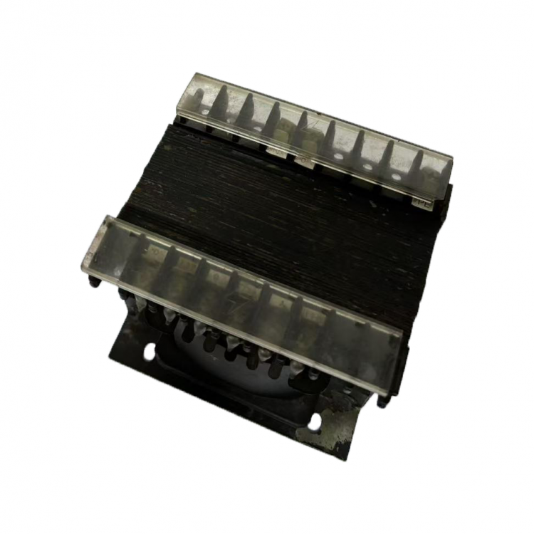
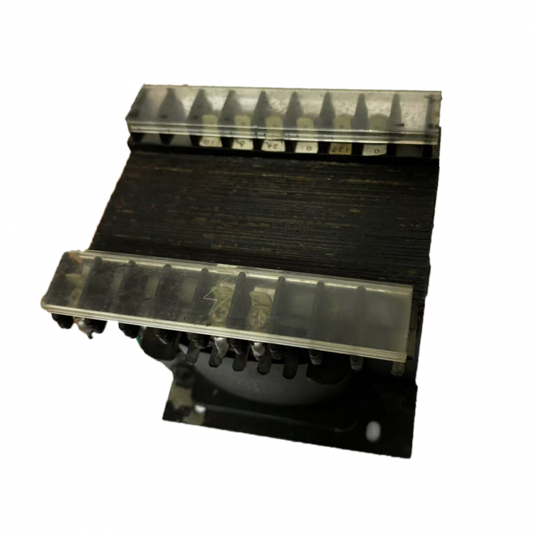
4. Basic Structure
The basic structure of control transformers includes the core, primary winding, secondary winding, control winding, and housing. The core is made of silicon steel sheets to enhance magnetic permeability and reduce iron losses. The primary winding is for connecting to the power supply, the secondary winding is for outputting electrical power, and the control winding is for adjusting the output voltage. The housing protects the internal components and provides insulation and heat dissipation.
V. Technical Specifications
Rated Power: Typically measured in kilovolt-amps (kVA), indicating the stable power output level of the transformer.
Rated Voltage: The rated voltage is present on both the high voltage winding and the low voltage winding, indicating the designed voltage of the transformer.
Turns Ratio: The ratio between the voltage of the high-voltage winding and the voltage of the low-voltage winding, which can be designed and adjusted as required.
Frequency: Typically 50Hz or 60Hz.
Technical Requirements for Control Transformers
Technical Specifications:
Rated Voltage: The rated voltage of the control transformer varies depending on the specific model and application scenario, typically 1000V and below.
Frequency: Typically 50Hz or 60Hz.
Efficiency: The efficiency of the transformer should reach 97% or higher.
Insulation Resistance: In the cold state, the insulation resistance should not be less than 10 MΩ; in the hot and damp state, the insulation resistance should not be less than 2 MΩ.
Electrical insulation strength: Should withstand a withstand voltage test under AC 50 Hz, 2000 V sine wave voltage, without breakdown or arc-over for 1 minute.
Leakage current: Not to exceed 3mA.
Winding temperature rise: The maximum temperature rise of the winding (E grade insulation) must not exceed 75 K (measured by the resistance method); the maximum temperature rise of the core (E grade insulation) must not exceed 55 K (measured by the semiconductor spot thermometer method).
Safety Requirements:
The transformer should have a dedicated terminal for grounding, marked with a grounding symbol.
Transformers should be used within the specified temperature and humidity range; the maximum surrounding air temperature should not exceed +40°C, with the average value not to surpass +35°C over 24 hours; the minimum temperature should be -5°C.
The installation location's altitude does not exceed 2000m.
Before purchasing, estimate the total power capacity of the appliances and leave some room for error to prevent transformers from being damaged upon instant startup.
Application Scope
Electrical Applications:
Control transformers are mainly used in AC circuits of 50Hz (or 60Hz) and voltage up to 1000V, where they can operate continuously for long periods under rated load.
Commonly used in machine tools and machinery as the power supply for electrical control lighting and indicator lights.
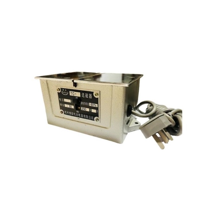
Equipment Type:
It is a small dry-type transformer, commonly used as a power supply for local lighting, signal lights, or indicator lights.
Used as the power supply for control circuits in electrical equipment, also serves as an isolation transformer for devices such as vacuum tube amplifiers, vacuum tube radios, and oscilloscopes.
Special Requirements:
When the working voltage of the power supply is greater than 220V, or when other voltages of the power supply are not suitable for the control purpose, a control transformer can be used for adjustment.
When voltage control is required that differs from the power source voltage, especially for low voltage control applications, a control transformer is the ideal choice.
In scenarios without a neutral line in the power supply or when a completely earth-insulated control power is required, control transformers can also play a significant role.